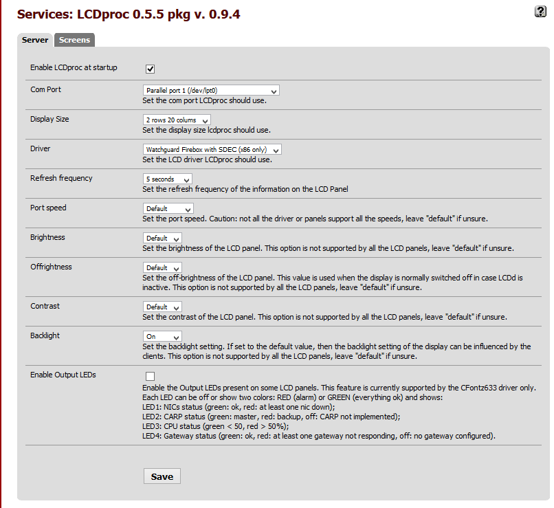
Gauge Pod 2.0 – Sender (pt 2)

I’ve spent about 2 days on dealing with the ADC (Analog to Digital Converter) of the Arduino platform. Turns out there’s more problems to overcome when dealing with taking analog signal from a sensor and converting it to meaningful digital reading.

The issue is that even with a constant input voltage the ADC reading sampling error rate is larger than I’d like (~1.2%) with some random spikes in excess of 3%.

I built a test rig to troubleshoot the issue. Using constant input voltage and a potentiometer to simulate the analog input from a sensor.
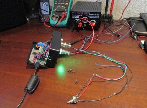
Goal:

– At least 4 sample updates per second. (Smooth gauge updates)
– Stable voltage regardless of outside interference.

Things I found:
– Arduino Atmel chip uses a single ADC and multiplexes the input pins.
– Switching read pin on the ADC causes noise in the system. Solution to read the first value and totally discard it. Then wait at least 10ms before sampling actual data.
– Sample accuracy is inversely proportional to the delay between samples. Shorter delay between reads, less drift. But over a static period of time, the error rate is the same.
– ADC is quite sensitive to electronic noise. Adjacent pins seem to affect reading.

Things I tried:

– Average voltage over multiple samples (currently 11 samples per read)
– Add delay between readings (1 to 12 ms) (currently 2ms)
– Discard top and bottom values and average the rest (currently discard 25%)
– Add a delta value, discard new value if difference is less than delta (currently 0.011V)
– vary delay on multiplex debounce (currently 10ms)

Current sampling rate: 3.7 samples / second.

Final Arduino Code:

const int LED_RED = 9;
const int LED_GREEN = 8;
const int LED_BLUE = 7;
const int LED_ACT = 11;
const int INPUT_REF = 22;
const int INPUT_RATE = 20;

int refPins[4] = {19, 17, 18, 16};
int sensePins[4] = {15, 13, 14, 12};
double lastRefVolts[4] = { 0, 0, 0, 0 };
double lastSenseVolts[4] = { 0, 0, 0, 0 };

const float LOW_VOLTAGE = 4.5; //alert voltage for 5V bus

const int MAX_SAMPLES = 50; //max sample on trim pot
const float DISCARD_PCT = 0.25; //percent of samples to discard (top and bottom)
const float MAX_DELTA = 0.011; //ignore changes less than this
const int SAMPLE_DELAY = 2; //delay MS between sample reads
const int INITIAL_DELAY = 10; //delay MS on pin change


void setup()
{
  
  //set pin IO modes
  pinMode(LED_RED, OUTPUT);
  pinMode(LED_GREEN, OUTPUT);
  pinMode(LED_BLUE, OUTPUT);
  pinMode(LED_ACT, OUTPUT);
  
  for (int pin = 0; pin < 4; pin++) 
  {
    pinMode(refPins[pin], INPUT);
    pinMode(sensePins[pin], INPUT);
  }
  
  pinMode(INPUT_REF, INPUT);
  pinMode(INPUT_RATE, INPUT); 
  
  //cycle leds
  digitalWrite(LED_RED, HIGH);
  digitalWrite(LED_BLUE, HIGH);
  digitalWrite(LED_GREEN, HIGH);

  setLED(LOW, HIGH, HIGH);
  delay(200);
  setLED(HIGH, LOW, HIGH);
  delay(200);
  setLED(HIGH, HIGH, LOW);
  delay(200);
  setLED(LOW, LOW, LOW);
  delay(200);
  setLED(HIGH, HIGH, HIGH);

  //emulated serial, speed ignored  
  Serial.begin(38400);
  
}

void loop()
{
    
   //read serial to clear buffer
  if (Serial.available() > 0)
  {
    Serial.flush(); 
  }

  //get number of samples to read
  int readCount = getReadCount();

  //write +5V bus voltage
  writeRefVoltage(readCount);

  //write all input sensors
  for (int pin = 0; pin < 4; pin++) {
    writeSerialVoltage(pin, readCount);
  }
  
}

void writeSerialVoltage(int pin, int readCount) 
{

  digitalWrite(LED_BLUE, HIGH); //blue off - start sending
  digitalWrite(LED_ACT, LOW); //internal off
    
  //ref volt, seems more volatile
  float refVolt = getVoltage(refPins[pin], readCount);
  float newRefVolt = processRefVoltage(pin, refVolt);

  //get sensor voltage
  float senseVolt = getVoltage(sensePins[pin], readCount);
  float newSenseVolt = processSenseVoltage(pin, senseVolt);


  Serial.print("IN");  //write identifier
  Serial.print(pin);
  Serial.print("\t");
  Serial.print(newRefVolt, 4); 
  Serial.print("\t");
  Serial.print(newSenseVolt, 4);
  Serial.print("\r");
  Serial.println("");
  
  digitalWrite(LED_ACT, HIGH); //internal on
  digitalWrite(LED_BLUE, LOW); //blue on - sending done

}

//do a delta comparison on Ref voltage
float processRefVoltage(int Pin, float refVolt) 
{
  
  float lastRefVolt = lastRefVolts[Pin];

   if (abs(refVolt - lastRefVolt) < MAX_DELTA)
     refVolt = lastRefVolts[Pin];
   else
     lastRefVolts[Pin] = refVolt;  
    
    return refVolt;

}

//do delta comparison on sensor voltage
float processSenseVoltage(int Pin, float senseVolt) 
{
  
  float lastSenseVolt = lastSenseVolts[Pin];

   if (abs(senseVolt - lastSenseVolt) < MAX_DELTA)
      senseVolt = lastSenseVolts[Pin];
  else 
     lastSenseVolts[Pin] = senseVolt;
    
    return senseVolt;
}


//send bus voltage to host
void writeRefVoltage(int readCount) {
  
  float refVoltage = getVoltage(INPUT_REF, readCount);
  
  if (refVoltage < LOW_VOLTAGE) 
  {
    digitalWrite(LED_RED, LOW);
    digitalWrite(LED_GREEN, HIGH);
  }
  else
  {
    digitalWrite(LED_RED, HIGH);
    digitalWrite(LED_GREEN, LOW);
  }
    
  Serial.print("REF\t");
  Serial.print(refVoltage, 4);
  Serial.println("");
}

//read value from ADC (0-1023) and convert to voltage (0-5)
float getVoltage(int PIN, int samples) {
  
  //allow ADC to stablize
  analogRead(PIN); //ignore value
  delay(INITIAL_DELAY); //wait for debounce
  
  float sampleList[samples]; 

  //read samples
  for (int i = 0; i < samples; i++) 
  {
    float voltage = (float)analogRead(PIN) * (5.0 / 1024.0);
    //round to 2 decimals
    sampleList[i] = (ceil(voltage * 100.0)) / 100.0;
    delay(SAMPLE_DELAY);
  }
  
   //sort array (shitty bubble sort, cause i'm lazy)
    float swapper;
    for (int o = samples-1; o > 0; o--) {
        for (int i = 1; i <= o; i++) {
          if (sampleList[i-1] > sampleList[i]) {
          swapper = sampleList[i-1];
          sampleList [i-1] = sampleList[i];
          sampleList[i] = swapper;
        }
      }
    }
      
      //discard % of top and bottom values, average the rest
      int avgStart = max(samples * DISCARD_PCT, 1); //array start
      int avgEnd = min(samples * (1.0 - DISCARD_PCT), samples); //array end
      
      int avgSamples = 0;
      float ret = 0;
      
      //average out the values
      for (int cntr = avgStart; cntr < avgEnd; cntr++) 
      {
        avgSamples++;
        ret += sampleList[cntr];
      }
     
      return ret / (float)avgSamples;
}

//read trim pot, get average samples
int getReadCount() {
 
  analogRead(INPUT_RATE);
  int readCount = analogRead(INPUT_RATE);
  return map(readCount, 0, 1023, 4, MAX_SAMPLES);
  
}


//set RGB led values
void setLED(int RED, int GREEN, int BLUE) {
digitalWrite(LED_RED, RED);
digitalWrite(LED_GREEN, GREEN);
digitalWrite(LED_BLUE, BLUE);
}

Binary sketch size: 7,196 bytes (of a 32,256 byte maximum)
Estimated memory use: 103 bytes (of a 2,560 byte maximum)

This is probably as close as I can get to get an accurate reading that doesn't jump around too much. Filters most noise while giving a decent sample rate. Currently reading all 4 inputs. Technically could reduce to 3 inputs since 4th won't be used for a while. Will see how well Gauge Pod software deals with current feed rate.
pfSense on Watchguard Firebox x5000

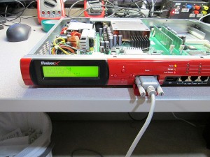
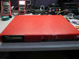
It’s been a while since I played around with firewalls. Picked up a really cheap Watchguard Firebox x5000 Peak on eBay. Could not resist taking the Peak platform for a spin with pfSense. I’ve heard good things about the power of the “Peak” platform. Even though the x5000 is older generation than the typical x550/x750s I’ve been playing with.

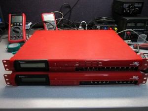
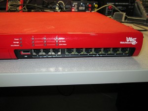
Unlike the x500 which comes with only 10/100 Realtek (problematic) interfaces. The x5000 is equipped with 3x 10/100/1000 nics and 8x 10/100 nics, all by Intel.

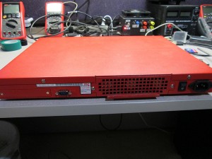
This box also comes with a second COM port at the rear of the unit. Though it serves no real purpose when running pfSense as all output is defaulted to COM1.

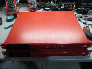
This firewall is actually just slightly shallower than the x750e series boxes. The x750 firewall is just a bit too deep for wall mount racks and required a right-angle power cable in order to fit. The x5000 is about an inch shorter.

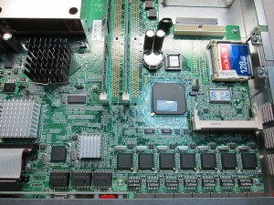
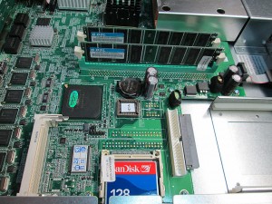
Taking the cover off exposes all the various components of this box. The Intel NIC chips can be clearly visible.

The “Peak” comes with 512MB of RAM standard. Unfortunately I could not locate any more DDR RAM to upgrade it, so for now will stick with the stock amount. I used to have tons of original DDR RAM modules, but got rid of them thinking I’m never gonna need them again.

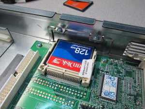
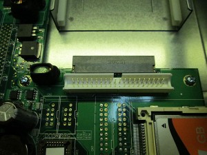
Just like most other boxes. This one comes with a 128MB Compact Flash card. And just like most of the other boxes, the IDE port is available for additional internal storage.

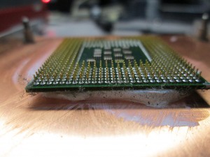
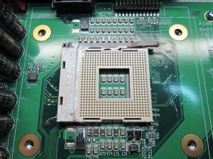
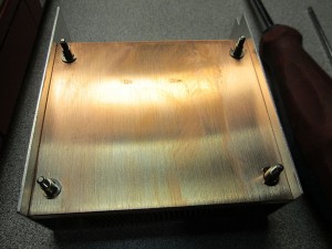
I wanted to take a quick peek at the CPU. Specifically to see what the stock CPU is. What I discovered was quite shocking. First of all, I had a problem getting the heatsink off from the CPU. Ended up tearing the heatsink and CPU directly from the ZIF socket. Closer examination revealed the cause of the problem. The amount of heat paste on this thing is insane. The gap between the heatsink and CPU was at least a couple of millimeters. It was everywhere. Someone really went to town on this sucker.

It took me almost 30 minutes to clean the CPU, heatsink and motherboard from all the thermal compound. I used plenty of rubbing alcohol and tons of cloths to get everything cleaned. Everything was completely covered with the goop.

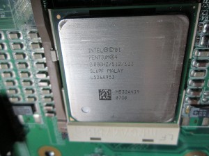
The CPU could finally be identified. Intel Pentium 4 2.8Ghz SL6PF. Not the most energy efficient CPU, quite the opposite. This firewall definitely sucks down a lot of juice. It’s actually a pretty fast CPU for the task. With firewalls raw speed matters most when dealing with latency. This one has plenty of speed.

Loading pfSense on this firewall is incredibly easy. There’s no BIOS flashing required. It boots pfSense from a 2GB CF card without any problems at all. Unlike the x500 firewall, which has Realtek NICs and randomly stops responding, the Intel NICs are bulletproof.

Once I got the firewall configured. It was time to do some throughput testing. I was expecting the speeds to be sub-par simply because both the 1000Mbit and 100Mbit interfaces are all on the PCI bus. PCIe did not exist in P4 era.

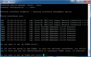
The interfaces on pfSense are identified as follows.
em0-em2 = 10/100/1000 NICs
fxp0-fxp6 = 10/100 NICs

Interestingly enough, the 8th 10/100 NIC does not appear in the list of devices. Not sure if this is due to pfSense limitation or a problem with the port itself.

On with the testing. The test was performed by copying a 8GB file between two machines. Both machines stored the file on an SSD to eliminate the disk as the bottleneck. The test was performed 3 times for each direction and values averaged over the test.

Source Interface Destination Interface Transfer Speed CPU Usage
fxp0 em0 10.3 MB/s 20%
em0 fxp0 11.5 MB/s 21%
em0 em1 42.8 MB/s 41%
em1 em0 97.8 MB/s 100% *
fxp0 fxp1 11.5 MB/s 27%
fxp1 fxp0 11.5 MB/s 27%

* pfSense UI interface stopped responding during the transfer.

Once again it’s been shown that the bottleneck is the PCI interface. With maximum theoretical speed of 133 MB/s shared across the PCI bus, the firewall will never be able to attain faster combined throughput than roughly 100 MB/s. This is not terrible though for a small network as that kind of saturation is rather rare. What I can’t explain is why pfSense shows different max speeds depending on direction of data. This technically shouldn’t make a difference. I saw the same thing happen when benchmarking the x550e firewalls.

In the end, this is actually a pretty sweet box for what it costs nowadays. Even with “only” 512MB of RAM it’d be sufficient to run a small rack. However I do not recommend it for office use. The fans run 100% speed all the time and are fairly loud, haven’t found a way to throttle the fans other than replacing them with something quieter. The box, running pfSense draws about 52W at idle and almost 100W under load.

GaugePod – Rev 2

I’ve been spending a lot of time lately thinking about how to best redo my GaugePod program for my Carputer project.

Existing Problems (and potential solutions):

Program sometimes crashes on resume from hibernate.
Need to determine what causes this. This started when upgraded from Atom to I3 Motherboard/CPU. Perhaps Mobo not sending proper signal to Windows?

Current Arduino implementation isn’t very accurate.
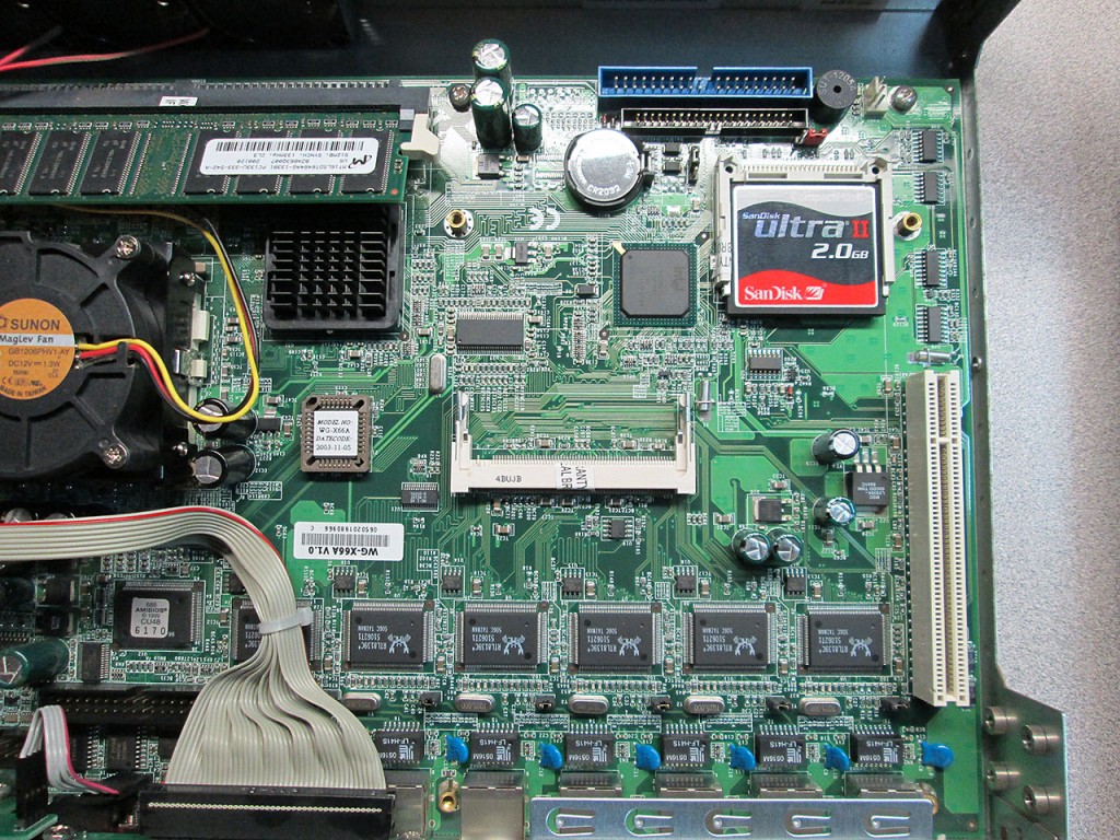
This one is major. Had to fudge the voltage numbers to get semi-accurate reading. This needs a rewrite. Right now the Arduino box simply sends the raw value from the ADC (0 to 1023) as input into GaugePod. Perhaps a better solution would be to have the Arduino send the actual voltage. In fact, I could monitor the reference voltage to make sure it doesn’t drop below 5V. Arduino could detect any drop in reference voltage and adjust reading before sending to the Carputer. Could even add an LED to indicate a condition where reference voltage is not 5V, though it wouldn’t know if input voltage is >5V. Though that is highly unlikely as the reference voltage is coming from a 5V voltage regulator.

Change how GaugePod stores settings locally.
Right now the settings are stored in a DataSet that’s stored in the user profile. Can’t migrate settings or even hand edit. Need the ability to import/export settings. Switch to XML Format. Will have to write a custom library to deal with this. Won’t be difficult. Already did this kind of implementation in the UltraDMM project.

The Arduino box is too big and wiring too complex.
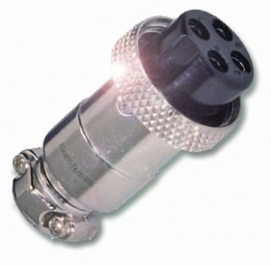
Need to simplify wiring, switch to Teensy for smaller footprint. Perhaps add chokes to eliminate electronics noise. Rev 2.0 of the Arduino box uses Molex connectors for the sensors.
Better to use barrel connectors. Need 3 Pins.
1 – 5V Input
2 – Ground
3 – Sensor Return
Something like this would work:

Additional advantage of using round connectors. Easy enough to drill holes for them rather then cut square holes for the Molex connectors. The enclosure would be nicer looking. The screw-in connectors would deal better with vibration in the car.

Program runs in foreground, blocks access to Centrifuse
Possible solution to implement as plugin for Centrifuse. Though it might be possible to simply run the program inside a Centrafuse window. I vaguely remember reading that this can be done. Drawback of this approach is reduced screen real-estate.
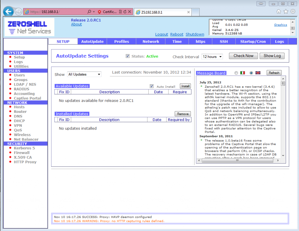
To Be Continued…..

pfSense on Watchguard Firebox – More Tweaks

There’s a known problem with pfSense 2.0.1 and Watchguard Firebox x750e and x1250e. Namely the additional 4 NIC interfaces have a tendency to drop out with a Watchdog error and the only remedy is to reboot the box. I came across a fix that seems to resolve the issue permanently. Been running for 2 weeks on the PCI-e interfaces without dropout. Previously I’d be luck to get 3 days on those.

The fix is to add these lines to /boot/loader.conf.local

hw.bce.tso_enable=0
hw.pci.enable_msix=0
hw.pci.enable_msi=0
net.inet.tcp.tso=0
hw.re.msi_disable=0
hw.re.msix_disable=0

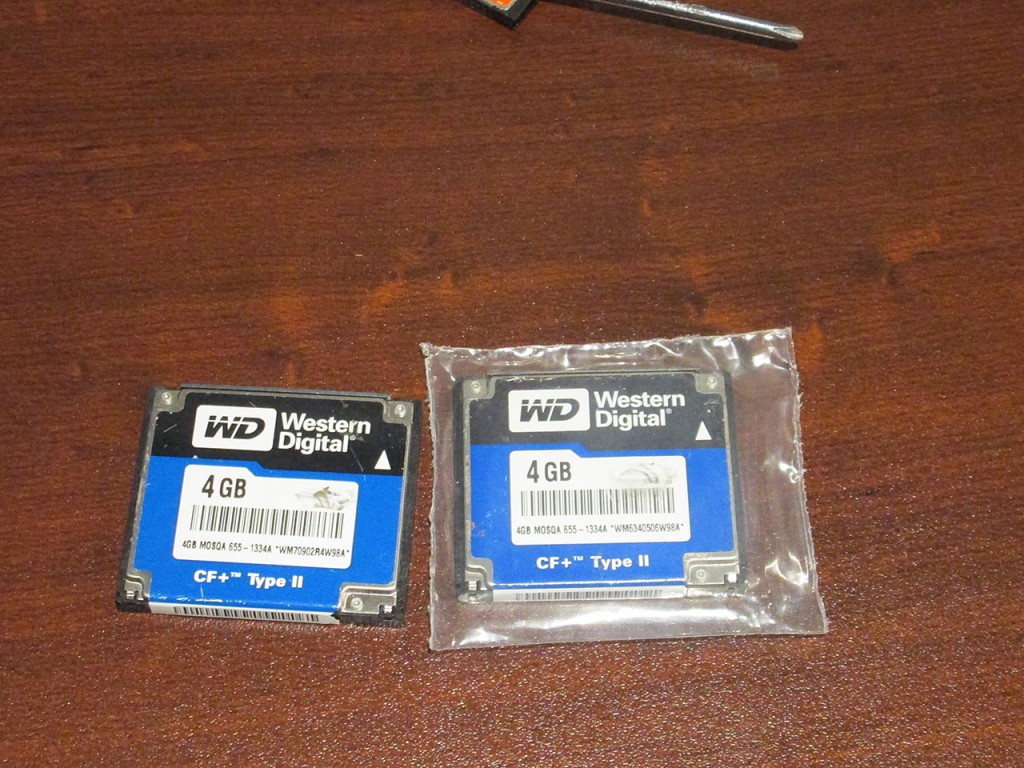
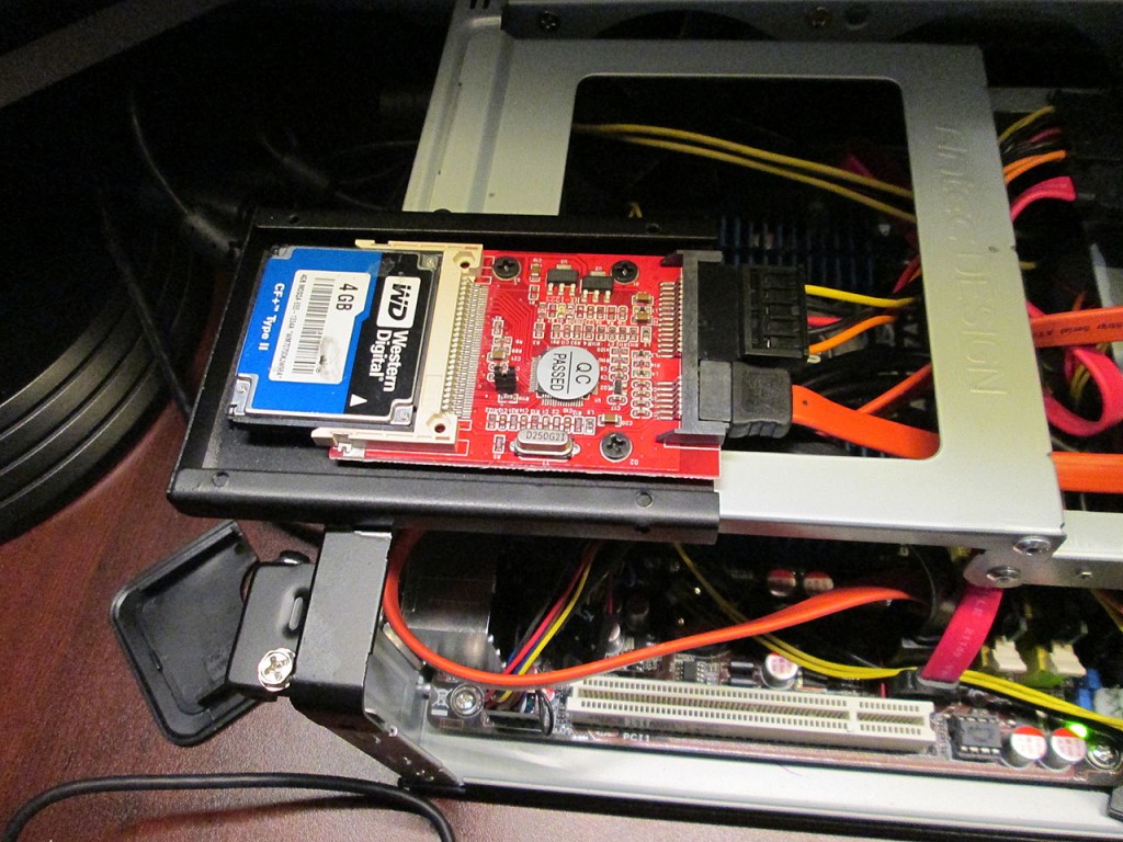
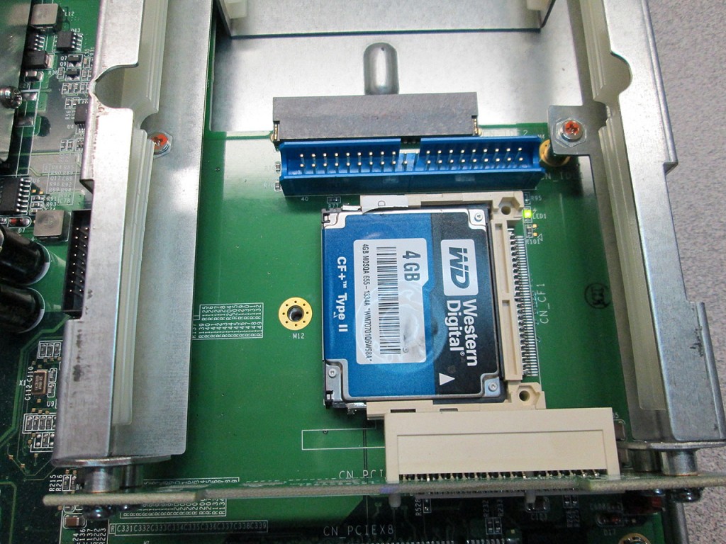
Additionally I picked up a few Western Digital 4GB MicroDrives from eBay. The idea behind this was to replace the flash based CF card in the firewall. In theory the MicroDrive does not have the write limitation of a Flash card so it could potentially store a lot more information on the card like logs, graphs, a/v definitions etc.

I had some problems getting the card read on the computer. First I tried reading directly with my multi card reader but it just went bonkers, wouldn’t read the card at all. Another card reader I had simply shut itself down when I plugged the drive in. I then tried a CF-to-SATA converter and plugged it into a Drive Toaster but after a few seconds it’d drop out. Lastly I tried to connect the drive directly to the computer. I eventually got it working by switching the BIOS from AHCI to SATA. One I got the drive detected properly, the method for loading the pfSense image onto it is the same as with a regular Compact Flash card. The only issue I ran into was when running “clean” on diskpart, the drive seemed to take forever to clean the partition.

Getting the card working on the x750e was effortless. The machine booted up with no issues. The boot process did take slightly longer which is understandable as this is a mechanical device with the same random IOP limit as a regular disk drive.

Netgear GS716T Fan Fix

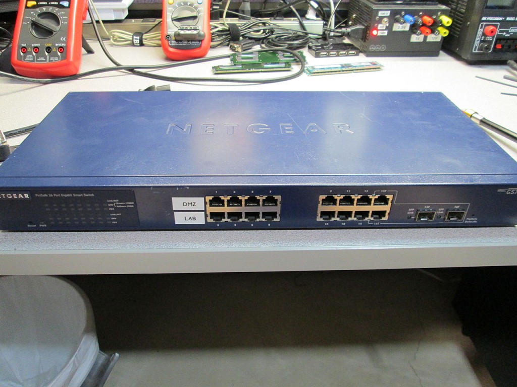
I’ve had this Netgear GS716T for about 5 years, even then I already bought it used from eBay. Couple of days ago the fans finally gave up the ghost. Replacing them is pretty trivial though as I’ve already replaced fans in several switches recently.

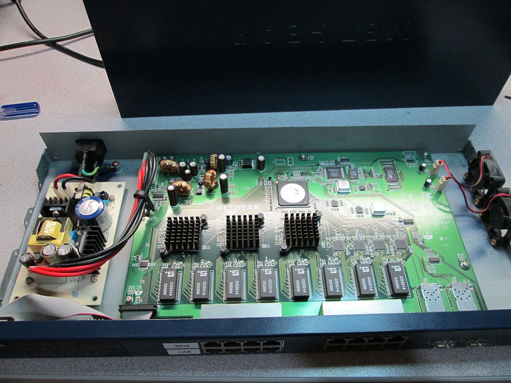
It’s easy enough to remove the cover as none of the screws are hidden and there are no “warranty void” stickers to remove.

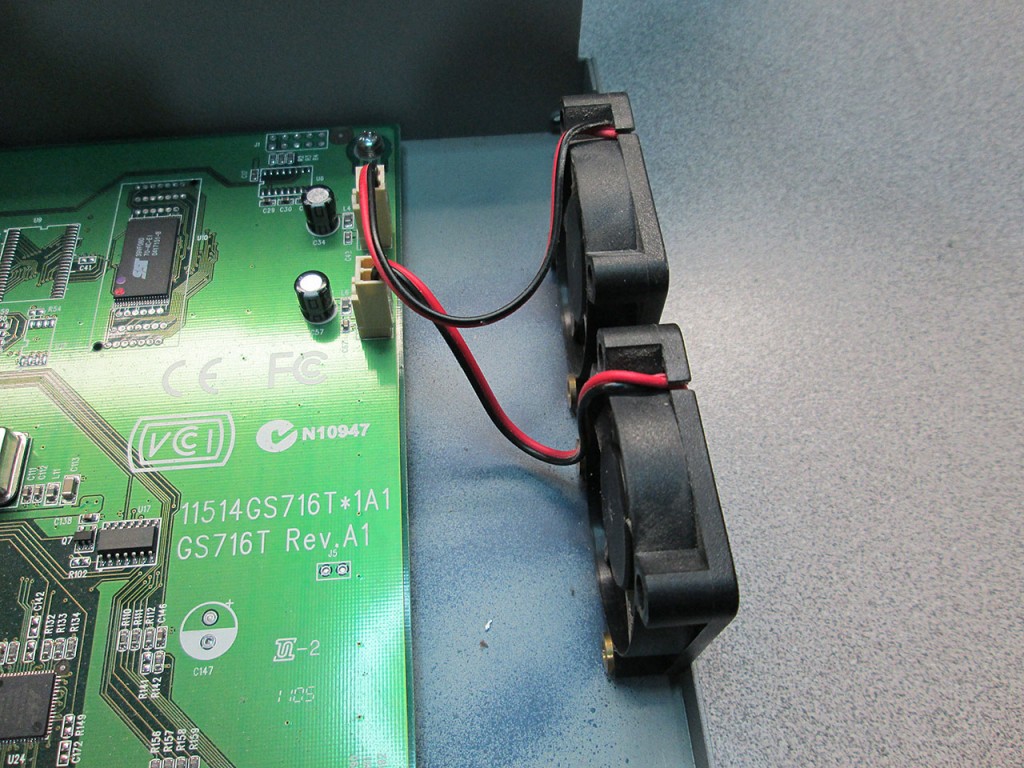
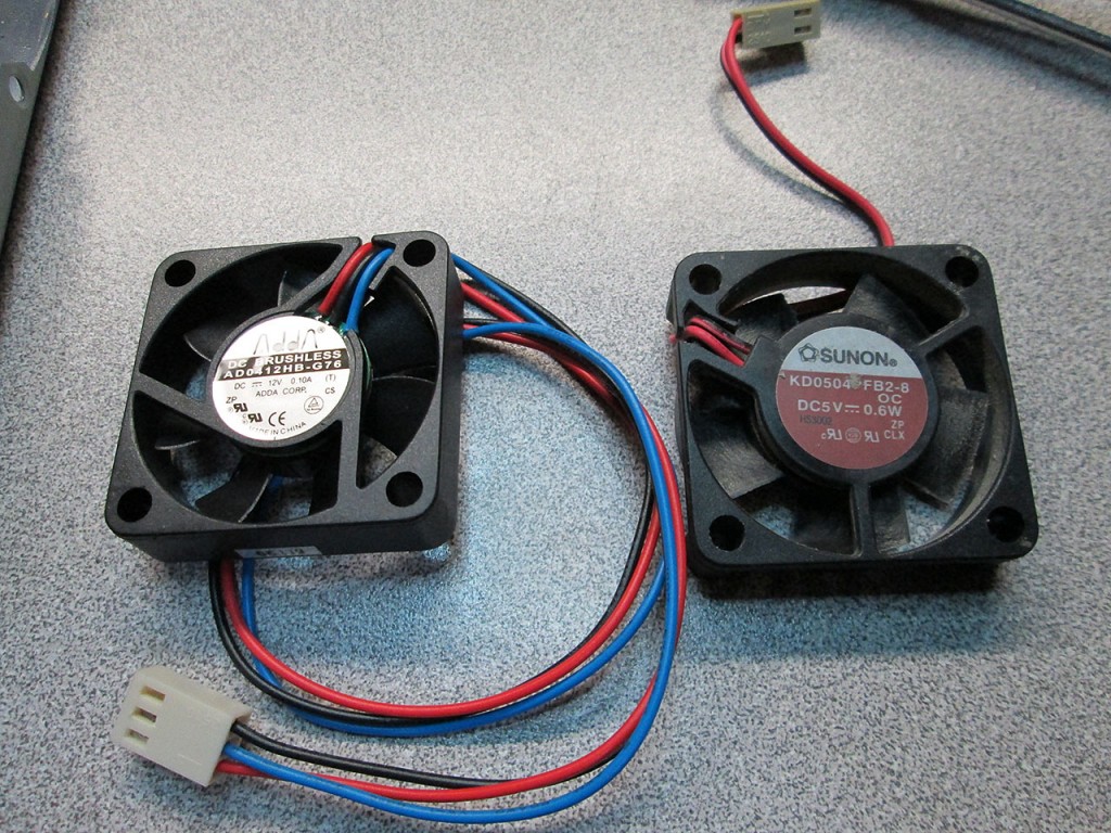
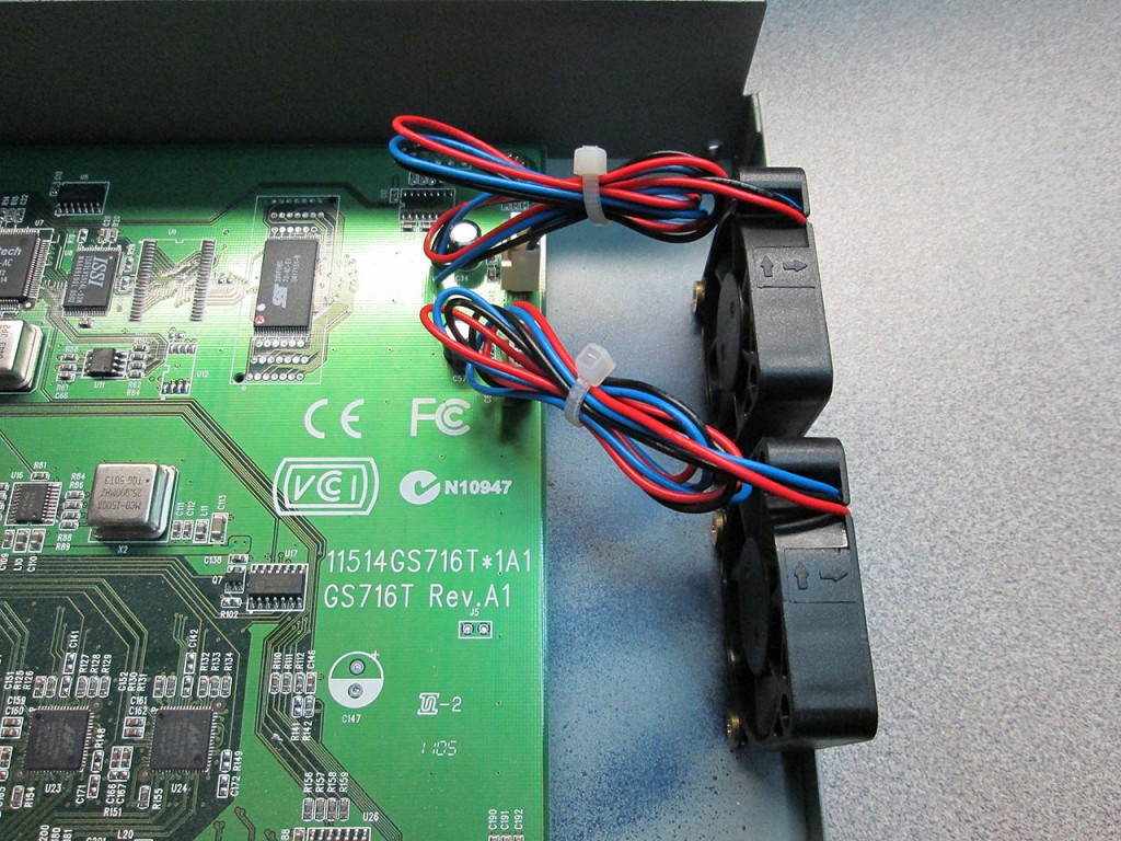
The two existing 40mm fans. Turns out one was completely dead, the other was just about to ready to quit via a rather noisy bearing.

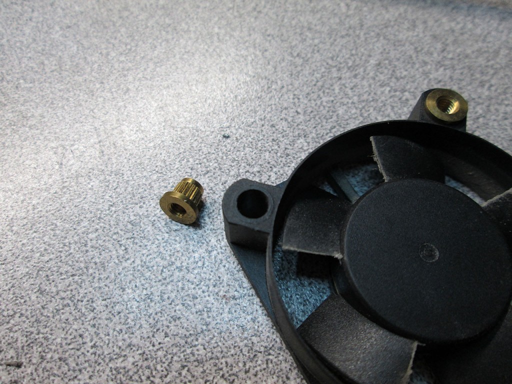
Interestingly enough, the fans are held in place via these “nuts” that get punched into the fan housing.

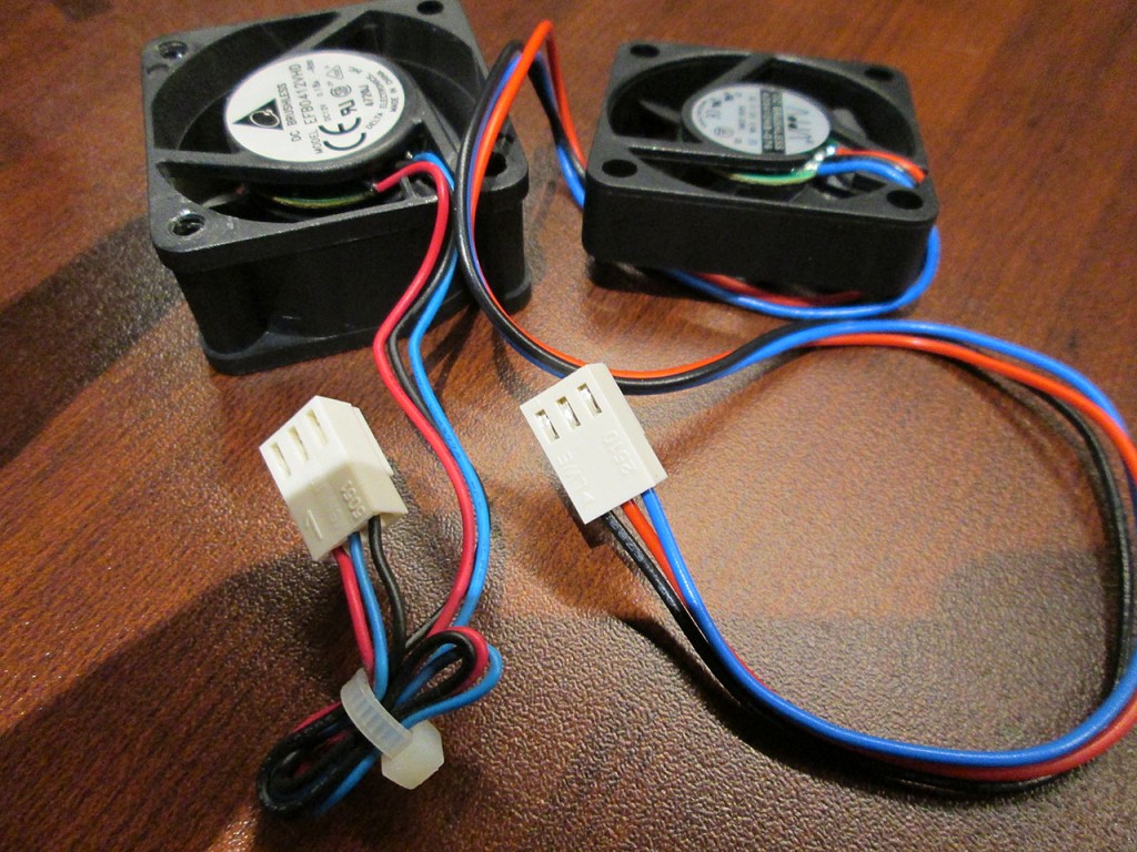
I’ve had few more 40mm fans laying around from my last Dell PowerConnect experiment. Same size but different specs. The new fans again are slightly slower / quieter than the original fans.

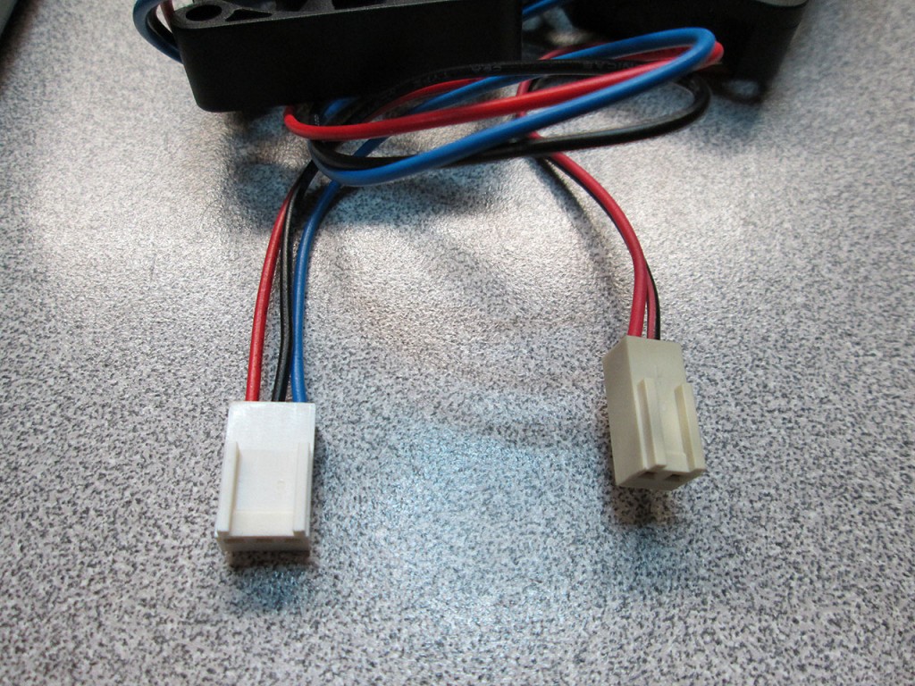
Once again had to pay attention to the pinout. Fortunately the GS716T does not use an RPM pin so it won’t even know if the fan is running slower or not.

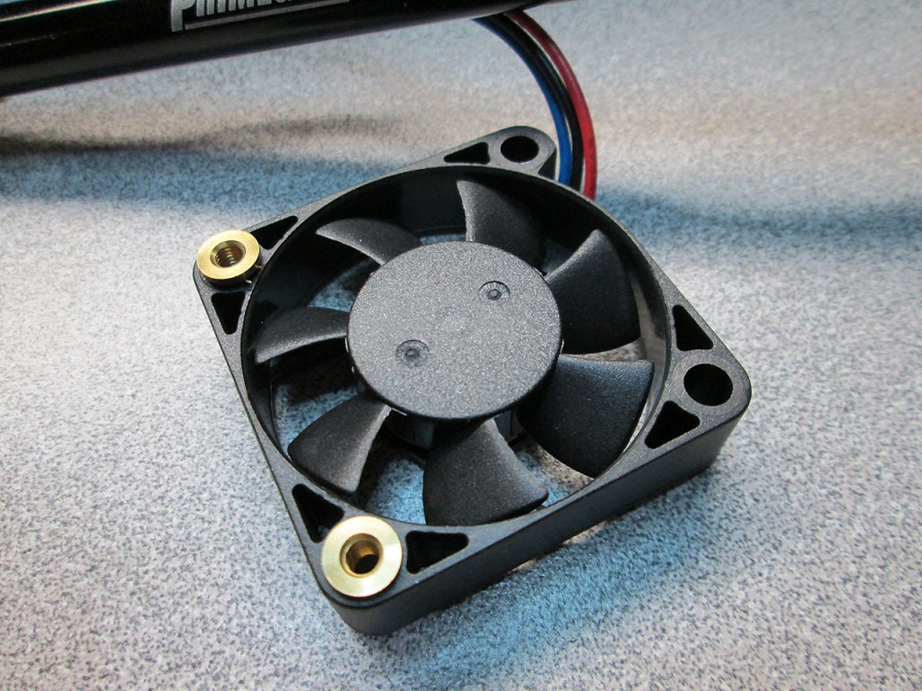
The fan mounts tapped back into the new fans. Took quite a bit of force to get these in.

New fans mounted in place and switch ready to be closed up. The whole process took maybe 30 minutes. Hopefully will get more life out of the switch yet. Not the greatest switch in the world but perfect for my lab environment.

Piece of Cake.

Fun with Fans

I’ve been running a Dell PowerConnect 5324 as my secondary switch at home that connects all the rooms together. The switch is rather loud in the location it’s sitting so I’ve decided to replace the fans in it to something quieter.

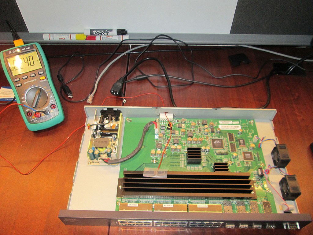
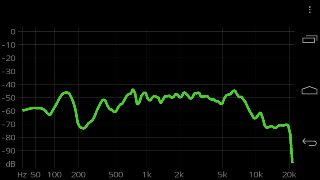
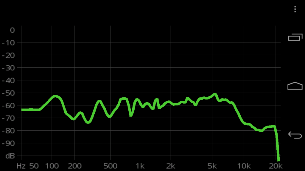
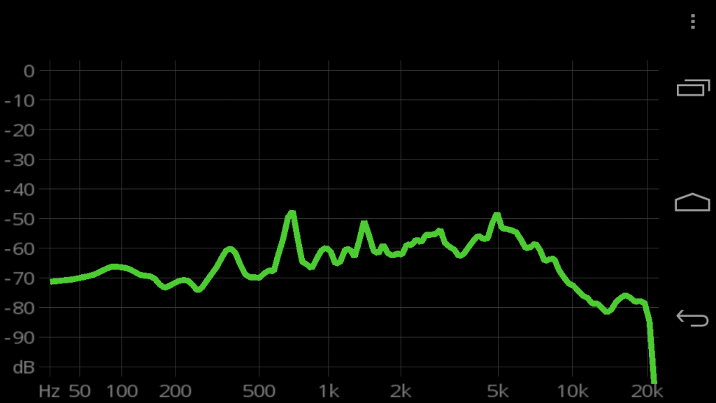
The switch uses 2 40mm high speed fans that exhaust air out of the enclosure. I had several 40mm fans that I could try to get the best noise/cooling ratio. I’ve used a digital multimeter with a thermal probe to measure the efficiency of the fans, my simple SPL meter to measure noise level and a simple Android app to measure the sound spectrum. The switch was ran for 30 minutes in each configuration to let the temperature of the switch settle.

Testing Methodology:
Ambient Noise: 23.3 dbA
Ambient Temperature: 23C

Configuration Temperature Sound Level
Stock Fan 26.2C 59.2 dBA

In the stock configuration the switch blasts out almost 64 dbA.

What would happen if I invert the fans so that they blow air into the switch?

Configuration Temperature Sound Level
Inverted Stock Fan 26.5C 63.7 dbA

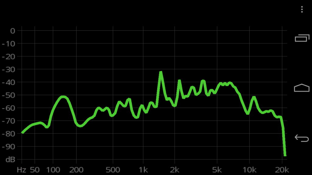
Wow. Definitely not an improvement. Not only this configuration is slightly louder. The fans emit a noise 1.5Khz range that’s very, very annoying.

The new fans are significantly thinner and operate at lower RPMs. They do not move quite as much air as the original fans.
A quick note about the fan pinout on the Dell PowerConnect 5324. The fan pins are actually non-standard and have to be swapped around. The Dell PowerConnect fans use Positive-Sense-Negative pinout as opposed to the standard Negative-Positive-Sense pinout. Connecting the fans incorrectly doesn’t seem to have any detrimental effect on the fans themselves (as I found out) but the fans will simply not operate.
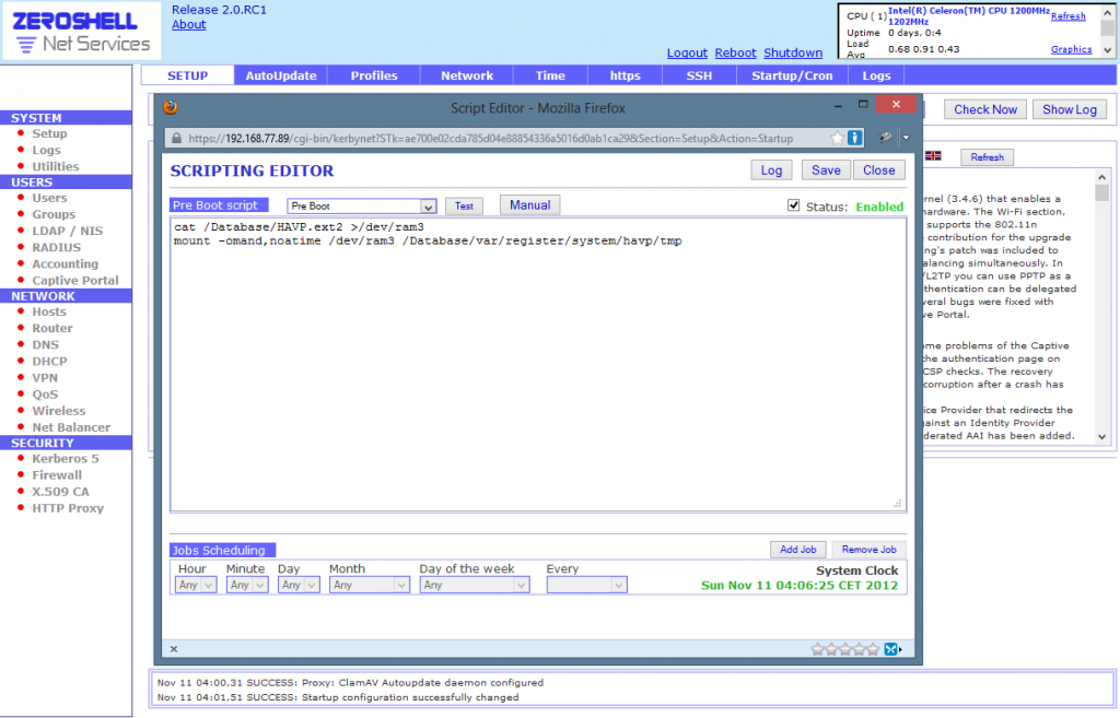
Once the fans were installed. I ran the test.

Configuration Temperature Sound Level
New Fan 27.4C 50.9 dbA

A 9.1 dbA drop is quite significant, that’s almost half as noisy as the original fans and the switch is now quieter than the ambient noise in the room the networking equipment is in. The temperature with the new fans running only went up a few notches.

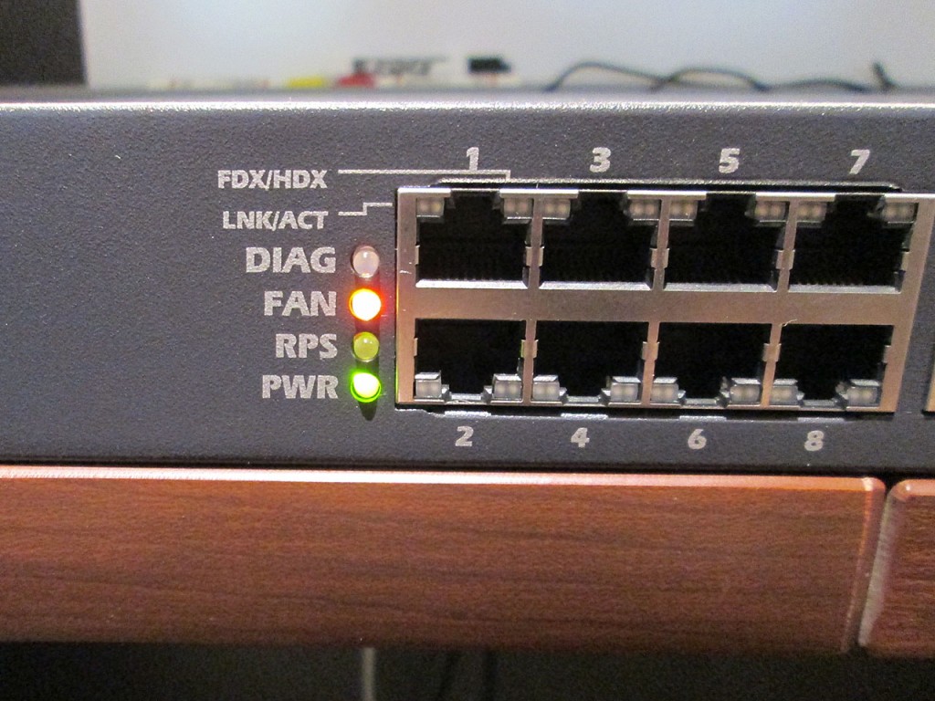
Unfortunately the switch did not like the reduced RPM on the fans. The Fan LED now blinks alternating red/green. However there doesn’t seem to be any performance degradation of the switch.

Even though this was the configuration I was most likely stick with, just for kicks, I’ve went ahead and tried the inverted fan configuration.

Configuration Temperature Sound Level
Inverted New Fan 27.9C 46.5 dbA

Even though in the inverted configuration the fans were quieter, the temperature went up a few more degrees and once again, the fans exhibited a noticeable whine 700hz range.
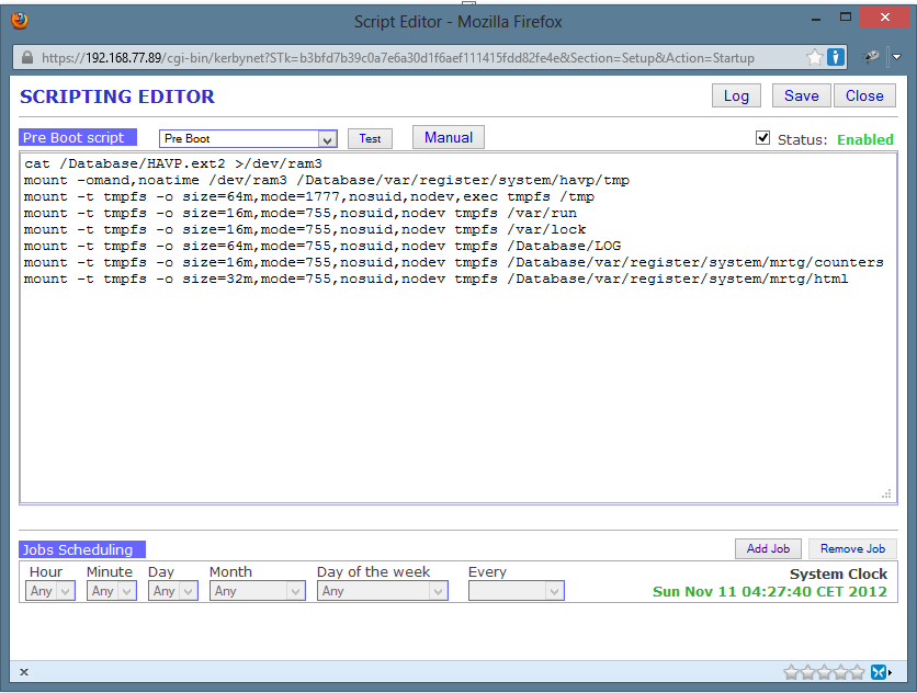
In the end I ended up going with the smaller fans in the same configuration as the stock fans, blowing air out of the switch. While slightly louder than the inverted configuration, it was lacking the whine which was quite noticable.
Watchguard x500 Hacking – Part 3 – ZeroShell

Another day, another opportunity to see what other firewall distros can be deployed on this old Watchguard Firebox x500. In this case I’ll try ZeroShell. I’ve used ZeroShell many times in the past, typically as a small VM. ZeroShell is one of the fastest and easiest Firewall Distros I’ve tried. Back in the day when I was trying to see if I can bond multiple cable modems together for site-to-site connections I’ve used ZeroShell due to it’s very easy bonding of OpenVPN connections.

Another reason why I’m eager to try ZeroShell on this Firebox is the fact that unlike pfSense and m0n0wall, it’s not BSD based OS. It’s actually linux based which means that there’s a very good possibility that the Watchdog Timeout issue might not happen as this seems to be a driver issue in BSD related to the Realtek NICs on the x500.

On to the install process.

Just like earlier first step is to simply load the firmware image onto the compact flash card. To do that once again need to clean the compact flash card from any existing partitions

Microsoft Windows [Version 6.2.9200]
(c) 2012 Microsoft Corporation. All rights reserved.

C:\Windows\System32>diskpart

Microsoft DiskPart version 6.2.9200

Copyright (C) 1999-2012 Microsoft Corporation.
On computer: ARES

DISKPART> list disk

  Disk ###  Status         Size     Free     Dyn  Gpt
  --------  -------------  -------  -------  ---  ---
  Disk 0    Online          238 GB      0 B
  Disk 1    Online           74 GB      0 B   *
  Disk 2    Online           74 GB      0 B   *
  Disk 3    Online           74 GB      0 B   *
  Disk 4    Online         2048 MB      0 B
  Disk 5    Offline        1024 GB      0 B        *
  Disk 6    Online          500 GB  1024 KB   *
  Disk 7    Online         1024 GB      0 B        *

DISKPART> select disk 4

Disk 4 is now the selected disk.

DISKPART> clean

DiskPart succeeded in cleaning the disk.

DISKPART> exit

Leaving DiskPart...

C:\Windows\System32>

Then use physdiskwrite to write the image onto the card. In this case the image being loaded is the ALIX image that can be downloaded here. The latest image (RC1) requires a minimum 2GB Compact Flash card to write the image to. Luckily I still have a few of those laying around.

Microsoft Windows [Version 6.2.9200]
(c) 2012 Microsoft Corporation. All rights reserved.

c:\2>physdiskwrite.exe ZeroShell-2.0.RC1-Alix-2GB.img

physdiskwrite v0.5.2 by Manuel Kasper 
Which disk do you want to write? (0..7) 4
About to overwrite the contents of disk 4 with new data. Proceed? (y/n) y

c:\2>

Once the compact flash card is installed into the firewall, connect the serial cable and use a terminal program at 38400-8-n-1 to watch the bootup process. During my bootup there seemed to be some errors at runtime that actually took a few seconds longer to get going.

ΓΏ[    1.004441] platform pc8736x_gpio.0: no device found
[   31.842568] ata1.00: exception Emask 0x0 SAct 0x0 SErr 0x0 action 0x6 frozen
[   31.863676] ata1.00: failed command: READ DMA
[   31.876728] ata1.00: cmd c8/00:08:00:00:00/00:00:00:00:00/e0 tag 0 dma 4096 in
[   31.876732]          res 40/00:00:00:00:00/00:00:00:00:00/00 Emask 0x4 (timeout)
[   31.920494] ata1.00: status: { DRDY }
[   62.960333] ata1.00: exception Emask 0x0 SAct 0x0 SErr 0x0 action 0x6 frozen
[   62.961451] ata1.00: failed command: READ DMA
[   62.966530] ata1.00: cmd c8/00:08:00:00:00/00:00:00:00:00/e0 tag 0 dma 4096 in
[   62.966534]          res 40/00:00:00:00:00/00:00:00:00:00/00 Emask 0x4 (timeout)
[   62.970295] ata1.00: status: { DRDY }
[   94.002083] ata1.00: exception Emask 0x0 SAct 0x0 SErr 0x0 action 0x6 frozen
[   94.003202] ata1.00: failed command: READ DMA
[   94.008282] ata1.00: cmd c8/00:08:00:00:00/00:00:00:00:00/e0 tag 0 dma 4096 in
[   94.008285]          res 40/00:00:00:00:00/00:00:00:00:00/00 Emask 0x4 (timeout)
[   94.012049] ata1.00: status: { DRDY }
Loading Zeroshell ZS-2.0.RC1 ...
DEVICE=/dev/sda2
Mounting ISO image  ...
mount: warning: /cdrom seems to be mounted read-only.
Loading root filesystem into RAM device... Success
mount: warning: /.root/cdrom seems to be mounted read-only.
Successfully mounted device ISO
INIT: version 2.85 booting
INIT: Entering runlevel: 3nterface...
[  OK  ] udevd daemon...
[  OK  ]ing for attached devices...
Checking for other PCI hardware ...
Loading  ...................................   [pata_acpi]
Loading  ...................................   [intel-rng]
Scanning for SCSI,SATA,IDE,USB storage devices...
--------------------------------------------------------------------
PROFILE   : Default Profile
Disk      : ATA       SanDiskSDCFH-20
Partition : sda3
Alias     : _DB.001
--------------------------------------------------------------------
[  OK  ]Time Zone  [Europe/Rome]
[  OK  ] Clock (LOCALTIME) --> System Time
[  OK  ]hostname to zeroshell.example.com
[  OK  ] configuration files...
[  OK  ]ng swap file...
Starting X.509 Certification Authority...
Generating zeroshell.example.com host certificate ...
Generating a 2048 bit RSA private key
...........................................+++
............+++
writing new private key to '/tmp/x509default.key'
-----
Using configuration from /etc/ssl/openssl.cnf
Check that the request matches the signature
Signature ok
Certificate Details:
        Serial Number: 3 (0x3)
        Validity
            Not Before: Nov  9 22:43:38 2012 GMT
            Not After : Nov  9 22:43:38 2014 GMT
        Subject:
            organizationalUnitName    = Hosts
            commonName                = zeroshell.example.com
        X509v3 extensions:
            X509v3 Extended Key Usage:
                TLS Web Server Authentication, TLS Web Client Authentication
            X509v3 Subject Alternative Name:
                DNS:zeroshell.example.com, IP Address:192.168.250.254, IP Address:192.168.0.75
Certificate is to be certified until Nov  9 22:43:38 2014 GMT (730 days)

Write out database with 1 new entries
Data Base Updated
Generating admin user certificate ...
Generating a 2048 bit RSA private key
.........................................................+++
....+++
writing new private key to '/tmp/x509default.key'
-----
Using configuration from /etc/ssl/openssl.cnf
Check that the request matches the signature
Signature ok
Certificate Details:
        Serial Number: 4 (0x4)
        Validity
            Not Before: Nov  9 22:43:40 2012 GMT
            Not After : Nov  9 22:43:40 2014 GMT
        Subject:
            organizationalUnitName    = users
            commonName                = admin
        X509v3 extensions:
            X509v3 Key Usage:
                Digital Signature, Key Encipherment, Data Encipherment
            X509v3 Extended Key Usage:
                TLS Web Client Authentication, E-mail Protection
Certificate is to be certified until Nov  9 22:43:40 2014 GMT (730 days)

Write out database with 1 new entries
[  OK  ]e Updated
[  OK  ] LDAP daemon...
[  OK  ] DNS service...
[  OK  ] system log daemon...
[  OK  ] kernel log daemon...
[  OK  ]connection tracking modules (h323,ftp,sip,irc,pptp,tftp)
[  OK  ]NAT tracking modules (ftp,pptp)
[  OK  ]g Layer 7 protocol definitions (l7-protocols-2009-05-28)
Starting Firewall...
Starting Captive Portal ...
--> Gateway disabled
--> Web Login Authentication Server disabled
Starting Network...
Starting WiFi subsystem ...
--> No supported Wi-Fi hardware has been found.
Detecting ethernet interfaces...
ETH00 (hardware changed) :  Realtek Semiconductor Co., Ltd. RTL-8139/8139C/8139C+ (rev 20)
ETH01 (hardware changed) :  Realtek Semiconductor Co., Ltd. RTL-8139/8139C/8139C+ (rev 20)
ETH02 (new) :  Realtek Semiconductor Co., Ltd. RTL-8139/8139C/8139C+ (rev 20)
ETH03 (new) :  Realtek Semiconductor Co., Ltd. RTL-8139/8139C/8139C+ (rev 20)
ETH04 (new) :  Realtek Semiconductor Co., Ltd. RTL-8139/8139C/8139C+ (rev 20)
ETH05 (new) :  Realtek Semiconductor Co., Ltd. RTL-8139/8139C/8139C+ (rev 20)
Configuring interfaces...
ETH00: 192.168.0.75/255.255.255.0
VPN99: 192.168.250.254/255.255.255.0
Starting Routing...
Starting Quality of Service on:
   NONE. No interfaces configured for QoS
[  OK  ] NTP daemon...
[  OK  ] Dynamic DNS client daemon...
[  OK  ] Log Watcher...
Starting Kerberos 5 KDC
[  OK  ]istribution Center process
[  OK  ]n administration process
[  OK  ] httpd daemon...
Checking HTTP Transparent Proxy and AntiVirus configuration...
[  OK  ] cron daemon ...
Starting MRTG ...
[  OK  ]ing MRTG ...
[  OK  ] Daemon Watcher ...
[  OK  ] AutoUpdate daemon...
Zeroshell
[  OK  ] caching background process ...
-------------------------------------------------------------------------------
 Z e r o S h e l l - Net Services  2.0.RC1          November 09, 2012 - 23:43
-------------------------------------------------------------------------------
  Hostname : zeroshell.example.com
  CPU (1)  : Intel(R) Celeron(TM) CPU                1200MHz  1202MHz
  Kernel   : 3.4.6-ZS
  Memory   : 512388 kB                          http://192.168.0.75
  Uptime   : 0 days, 0:2                        User     : admin
  Load     : 2.12 0.89 0.33                     Password : zeroshell
  Profile  : Default Profile
-------------------------------------------------------------------------------
 COMMAND MENU
   Activate Profile              

Change admin password Deactivate Profile Show Routing Table Shell Prompt Show Firewall Rules Reboot Show Network Interface Shutdown Fail-Safe Mode Create a Bridge IP Manager WiFi Manager Select:

Now that the firewall is up. I configured the WAN and LAN interfaces via the shell. By default the DHCP server on LAN side is not enabled so in order to access the firewall via the browser I had to set a static IP address on my machine. Once the IP has been configured, just launch a the browser and point to the address as displayed in the console (default http://192.168.0.75)

I also disovered that by default the WAN interface allows access to the ZeroShell interface also, and since the firewall WAN is actually on my LAN, I was able to access and configure the UI from my workstation. This also means that it’s very important to change the default password if the firewall is internet facing as anyone coming across it can reconfigure it.

Running some unencrypted performance tests. I was able to achieve 11.9MB/s (95.2 Mbit/s) throughput across the firewall. This is actually not bad considering the same test on this box running pfSense the throughput was 11.1MB/s.

I came across an interesting article on the ZeroShell forums about the HTTP Anti-Virus Proxy and Compact Flash cards. Specifically about the HAVP’s work directory being used during its operation. To create a RAM drive to store these temporary files instead shut down HAVP and execute these commands from console or through SSH:

root@zeroshell root> cd /Database
root@zeroshell Database> dd if=/dev/zero of=HAVP.ext2 count=100000
100000+0 records in
100000+0 records out

root@zeroshell Database> mkfs.ext2 HAVP.ext2
mke2fs 1.42 (29-Nov-2011)
HAVP.ext2 is not a block special device.
Proceed anyway? (y,n) y
Discarding device blocks: done
Filesystem label=
OS type: Linux
Block size=1024 (log=0)
Fragment size=1024 (log=0)
Stride=0 blocks, Stripe width=0 blocks
12544 inodes, 50000 blocks
2500 blocks (5.00%) reserved for the super user
First data block=1
Maximum filesystem blocks=51380224
7 block groups
8192 blocks per group, 8192 fragments per group
1792 inodes per group
Superblock backups stored on blocks:
        8193, 24577, 40961

Allocating group tables: done
Writing inode tables: done
Writing superblocks and filesystem accounting information: done

root@zeroshell Database> mount -o loop HAVP.ext2 /mnt
root@zeroshell Database> chown havp.havp /mnt
root@zeroshell Database> umount /mnt
root@zeroshell Database> cat /Database/HAVP.ext2 > /dev/ram3
root@zeroshell Database> mount -omand,noatime /dev/ram3 /Database/var/register/system/havp/tmp
root@zeroshell Database>

The last two lines have to be added to the pre-boot script so that they execute on device restart.

Now just restart the HAVP service and it’s done.

After more than 24 hours of various traffic passing through the firewall, I have not had any issues yet with the Watchguard Timeout. So far so good. The firewall performs pretty well. There’s probably no chance getting the LCD working easily at this point. Though there’s a small possibility that ZeroShell will at one point support LCDProc in which case the LCD can live again.

I have also since added few more remounts to ensure longer CF card life. Apparently just because the ZeroShell distro image is aimed at embedded devices, it still performs regular writes to the local storage. Since CF cards have limited write cycles, remounting the writeable locations in RAM drive should significantly extend the life of the Compact Flash card.

mount -t tmpfs -o size=64m,mode=1777,nosuid,nodev,exec tmpfs /tmp
mount -t tmpfs -o size=16m,mode=755,nosuid,nodev tmpfs /var/run
mount -t tmpfs -o size=16m,mode=755,nosuid,nodev tmpfs /var/lock
mount -t tmpfs -o size=64m,mode=755,nosuid,nodev tmpfs /Database/LOG
mount -t tmpfs -o size=16m,mode=755,nosuid,nodev tmpfs /Database/var/register/system/mrtg/counters
mount -t tmpfs -o size=32m,mode=755,nosuid,nodev tmpfs /Database/var/register/system/mrtg/html

Watchguard x500 Hacking – Part 2 – m0n0wall

When I originally picked up the Watchguard Firebox x500, I only had the intention of trying pfSense on it. But now that I have pfSense running succesfully on the next generation Watchguard Fireboxes (x550e, x750e and 1250e). I figured might as well try m0n0wall on it (and some other OSs later). One particular reason why I’m interested in trying other firewall software on the Watchguard is that there’s a known problem with the Realtek NIC’s on the x500 and the current pfSense version (2.0). The firewall will randomly issue “watchdog timeout” error and then simply stop responding to traffic. Rebooting the firewall seems to be the only way to get it moving again.

From a little bit of research, getting m0n0wall running on x500 is just as trivial as getting pfSense running. As an added bonus, the m0n0wall image is much smaller than the pfSense image and the original Compact Flash card can be used. The embedded image for version 1.33 comes in at only 7.6 MB.

Loading the m0n0wall image onto the compact flash is identical to pfSense.

Step 1. Clean the CF Card


C:\>diskpart

Microsoft DiskPart version 6.2.9200

Copyright (C) 1999-2012 Microsoft Corporation.
On computer: ARES

DISKPART> list disk

  Disk ###  Status         Size     Free     Dyn  Gpt
  --------  -------------  -------  -------  ---  ---
  Disk 0    Online          238 GB      0 B
  Disk 1    Online           74 GB      0 B   *
  Disk 2    Online           74 GB      0 B   *
  Disk 3    Online           74 GB      0 B   *
  Disk 4    Online          122 MB      0 B
  Disk 5    No Media           0 B      0 B
  Disk 6    No Media           0 B      0 B
  Disk 7    No Media           0 B      0 B
  Disk 8    Offline        1024 GB      0 B        *
  Disk 9    Online          500 GB  1024 KB   *
  Disk 10   Online         1024 GB      0 B        *

DISKPART> select disk 4

Disk 4 is now the selected disk.

DISKPART> clean

DiskPart succeeded in cleaning the disk.

DISKPART> exit

Leaving DiskPart...

C:\>

Step 2. Load m0n0wall image onto the card
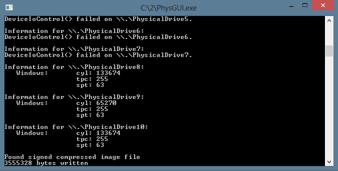
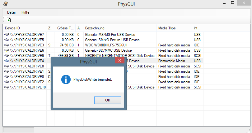
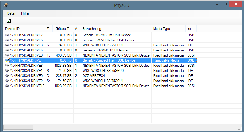
Once again I used physdiskwrite + PhysGUI to load the image onto the card.

Select the proper disk

The disk image is being written to the CF card

And we’re done.

Now just a matter of taking the Firebox cover off and plugging in the new CF card. Once that’s done. Connect a serial cable to the console at 115200-8-n-1 and watch the boot process.

Step 3. Configure m0n0wall.

Copyright (c) 1992-2008 The FreeBSD Project.
Copyright (c) 1979, 1980, 1983, 1986, 1988, 1989, 1991, 1992, 1993, 1994
        The Regents of the University of California. All rights reserved.
FreeBSD is a registered trademark of The FreeBSD Foundation.
FreeBSD 6.4-RELEASE-p5 #0: Sun Jan  9 22:24:57 CET 2011
    root@mb64.neon1.net:/usr/src/sys/i386/compile/M0N0WALL_EMBEDDED
Timecounter "i8254" frequency 1193182 Hz quality 0
CPU: Intel(R) Celeron(TM) CPU                1200MHz (1202.73-MHz 686-class CPU)
  Origin = "GenuineIntel"  Id = 0x6b4  Stepping = 4
  Features=0x383f9ff
real memory  = 536870912 (512 MB)
avail memory = 499331072 (476 MB)
wlan: mac acl policy registered
ath_hal: 0.9.20.3 (AR5210, AR5211, AR5212, RF5111, RF5112, RF2413, RF5413)
cpu0 on motherboard
pcib0:  pcibus 0 on motherboard
pir0:  on motherboard
$PIR: Using invalid BIOS IRQ 9 from 2.13.INTA for link 0x63
pci0:  on pcib0
pcib1:  at device 30.0 on pci0
pci2:  on pcib1
re0:  port 0xd500-0xd5ff mem 0xefefa000-0xefefa1ff irq 10 at device 9.0 on pci2
miibus0:  on re0
rlphy0:  on miibus0
rlphy0:  10baseT, 10baseT-FDX, 100baseTX, 100baseTX-FDX, auto
re0: Ethernet address: 00:90:7f:31:cc:60
re0: [FAST]
re1:  port 0xd600-0xd6ff mem 0xefefb000-0xefefb1ff irq 5 at device 10.0 on pci2
miibus1:  on re1
rlphy1:  on miibus1
rlphy1:  10baseT, 10baseT-FDX, 100baseTX, 100baseTX-FDX, auto
re1: Ethernet address: 00:90:7f:31:cc:61
re1: [FAST]
re2:  port 0xd900-0xd9ff mem 0xefefc000-0xefefc1ff irq 11 at device 11.0 on pci2
miibus2:  on re2
rlphy2:  on miibus2
rlphy2:  10baseT, 10baseT-FDX, 100baseTX, 100baseTX-FDX, auto
re2: Ethernet address: 00:90:7f:31:cc:62
re2: [FAST]
re3:  port 0xda00-0xdaff mem 0xefefd000-0xefefd1ff irq 12 at device 12.0 on pci2
miibus3:  on re3
rlphy3:  on miibus3
rlphy3:  10baseT, 10baseT-FDX, 100baseTX, 100baseTX-FDX, auto
re3: Ethernet address: 00:90:7f:31:cc:63
re3: [FAST]
re4:  port 0xdd00-0xddff mem 0xefefe000-0xefefe1ff irq 9 at device 13.0 on pci2
miibus4:  on re4
rlphy4:  on miibus4
rlphy4:  10baseT, 10baseT-FDX, 100baseTX, 100baseTX-FDX, auto
re4: Ethernet address: 00:90:7f:31:cc:64
re4: [FAST]
re5:  port 0xde00-0xdeff mem 0xefeff000-0xefeff1ff irq 6 at device 14.0 on pci2
miibus5:  on re5
rlphy5:  on miibus5
rlphy5:  10baseT, 10baseT-FDX, 100baseTX, 100baseTX-FDX, auto
re5: Ethernet address: 00:90:7f:31:cc:65
re5: [FAST]
isab0:  at device 31.0 on pci0
isa0:  on isab0
atapci0:  port 0x1f0-0x1f7,0x3f6,0x170-0x177,0x376,0xff00-0xff0f at device 31.1 on pci0
ata0:  on atapci0
ata1:  on atapci0
pmtimer0 on isa0
orm0:  at iomem 0xe0000-0xe0fff on isa0
sio0 at port 0x3f8-0x3ff irq 4 flags 0x10 on isa0
sio0: type 16550A, console
sio1: configured irq 3 not in bitmap of probed irqs 0
sio1: port may not be enabled
unknown:  can't assign resources (memory)
unknown:  can't assign resources (port)
RTC BIOS diagnostic error 20
Timecounter "TSC" frequency 1202733613 Hz quality 800
Timecounters tick every 1.000 msec
Fast IPsec: Initialized Security Association Processing.
IP Filter: v4.1.33 initialized.  Default = block all, Logging = enabled
md0: Preloaded image  16777216 bytes at 0xc086b0e8
ad0: 122MB  at ata0-master PIO4
Trying to mount root from ufs:/dev/md0
kern.coredump: 1 -> 0
Found configuration on ad0.
re0: link state changed to DOWN
re1: link state changed to DOWN
re2: link state changed to DOWN
re3: link state changed to DOWN
re4: link state changed to DOWN
re5: link state changed to DOWN
Initializing timezone... done
Configuring firewall... done
Configuring LAN interface... done
Configuring WAN interface... done
Starting syslog service... done
Starting webGUI... done
Starting DNS forwarder... done
Starting DHCP service... done
Starting NTP client... done

There you have it, m0n0wall running on the x500. Now it’s just a matter of configuring the interfaces for WAN and LAN. In this case the “External” interface was used as WAN (re0) and the first interface as LAN (re1)


*** This is m0n0wall, version 1.33
    built on Wed Mar 16 12:01:42 CET 2011 for embedded
    Copyright (C) 2002-2011 by Manuel Kasper. All rights reserved.
    Visit http://m0n0.ch/wall for updates.


    LAN IP address: 192.168.1.1

    Port configuration:

    LAN   -> sis0
    WAN   -> sis1


m0n0wall console setup
**********************
1) Interfaces: assign network ports
2) Set up LAN IP address
3) Reset webGUI password
4) Reset to factory defaults
5) Reboot system
6) Ping host

Enter a number: 1

Valid interfaces are:

re0     00:90:7f:31:cc:60   (up)   RealTek 8139C+ 10/100BaseTX
re1     00:90:7f:31:cc:61   (up)   RealTek 8139C+ 10/100BaseTX
re2     00:90:7f:31:cc:62          RealTek 8139C+ 10/100BaseTX
re3     00:90:7f:31:cc:63          RealTek 8139C+ 10/100BaseTX
re4     00:90:7f:31:cc:64          RealTek 8139C+ 10/100BaseTX
re5     00:90:7f:31:cc:65          RealTek 8139C+ 10/100BaseTX

Do you want to set up VLANs first?
If you're not going to use VLANs, or only for optional interfaces, you
should say no here and use the webGUI to configure VLANs later, if required.

Do you want to set up VLANs now? (y/n) n

If you don't know the names of your interfaces, you may choose to use
auto-detection. In that case, disconnect all interfaces before you begin,
and reconnect each one when prompted to do so.

Enter the LAN interface name or 'a' for auto-detection: re1

Enter the WAN interface name or 'a' for auto-detection: re0

Enter the Optional 1 interface name or 'a' for auto-detection
(or nothing if finished):

The interfaces will be assigned as follows:

LAN  -> re1
WAN  -> re0

The firewall will reboot after saving the changes.

Do you want to proceed? (y/n) y

The firewall is rebooting now.
Waiting (max 60 seconds) for system process `vnlru' to stop...done
Waiting (max 60 seconds) for system process `bufdaemon' to stop...done
Waiting (max 60 seconds) for system process `syncer' to stop...
Syncing disks, vnodes remaining...0 done
All buffers synced.
Uptime: 36s
Rebooting...

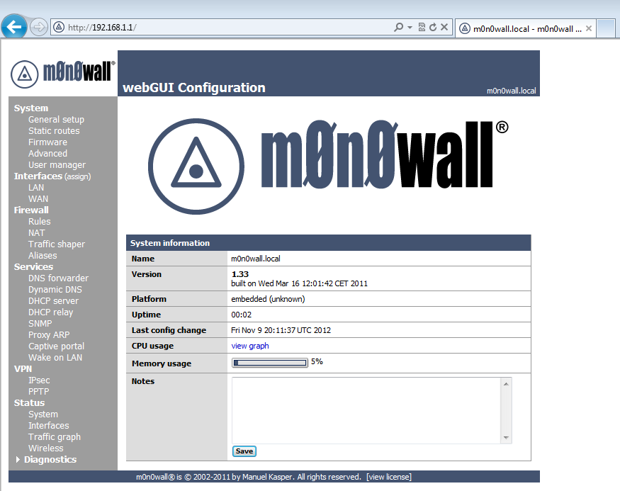
A few moments later the web UI was fully accessible and ready to be configured.

Unfortunately just a few moments later, while digging around the Web GUI the console showed the dreaded watchdog timeout error. And all network communication with the firewall and beyond has stopped.

*** This is m0n0wall, version 1.33
    built on Wed Mar 16 12:01:42 CET 2011 for embedded
    Copyright (C) 2002-2011 by Manuel Kasper. All rights reserved.
    Visit http://m0n0.ch/wall for updates.


    LAN IP address: 192.168.1.1

    Port configuration:

    LAN   -> re1
    WAN   -> re0


m0n0wall console setup
**********************
1) Interfaces: assign network ports
2) Set up LAN IP address
3) Reset webGUI password
4) Reset to factory defaults
5) Reboot system
6) Ping host

Enter a number: re1: watchdog timeout
re1: watchdog timeout

Well, so much for that idea..on to the next firewall….ZeroShell?

Enjoy The Silence

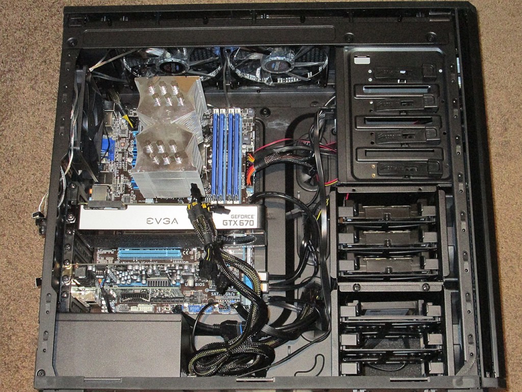
As part of my “quiet computing” innitiative I’ve recently upgraded my computer from a Coolermaster Centurion 590 case to the Corsair Obsidian 550D. The new Obsidian 550D case is purpose build silent case, with proper sound insulation, vibration reduction for HDD’s and Fans. Additional quiet upgrades were a fanless CPU heatsink and a couple of 140mm fans.

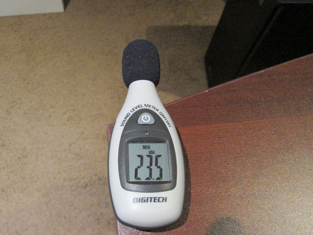
Just swapping the case caused a huge drop in ambient noise level. Using my “cheapie” eBay SPL meter the measured computer noise in my room went from 27.8 dBA to 25.1 dBA. This is based on ambient room noise of 23.5 dBA. The last bit of noise was coming from the EVGA GTX 470 video card.

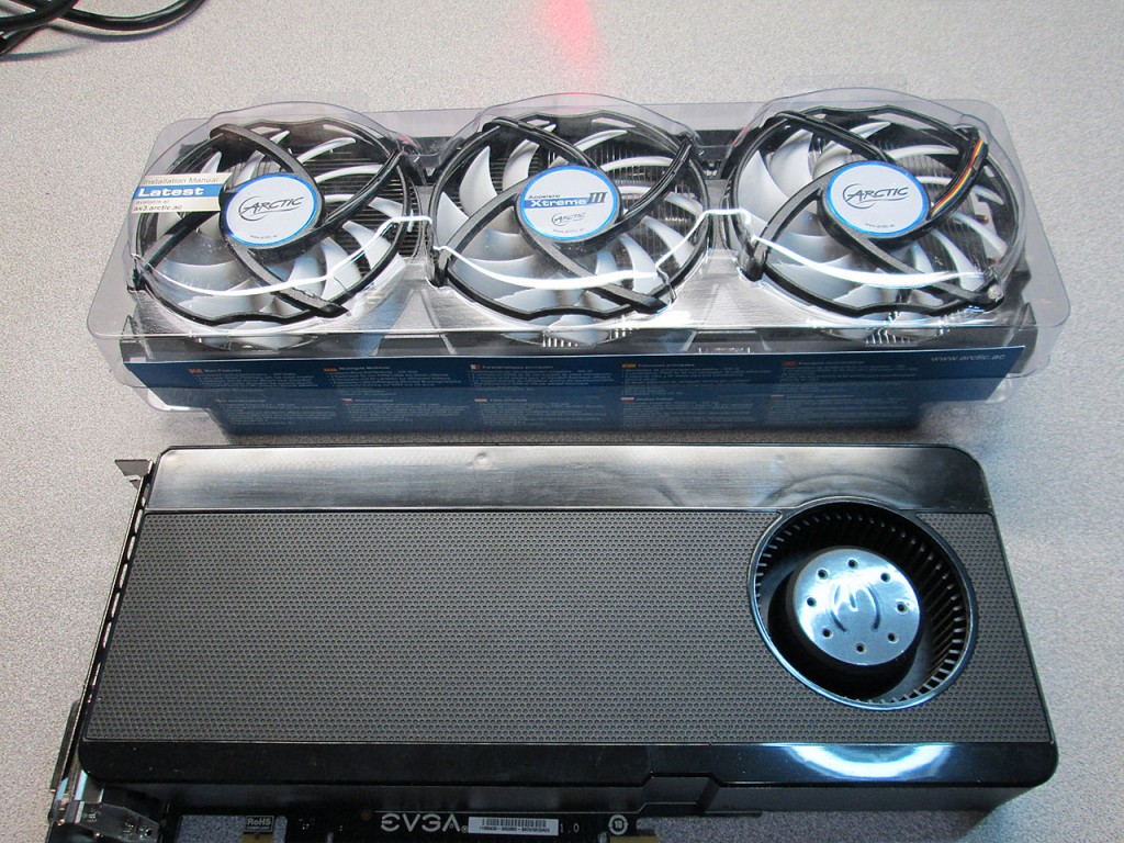
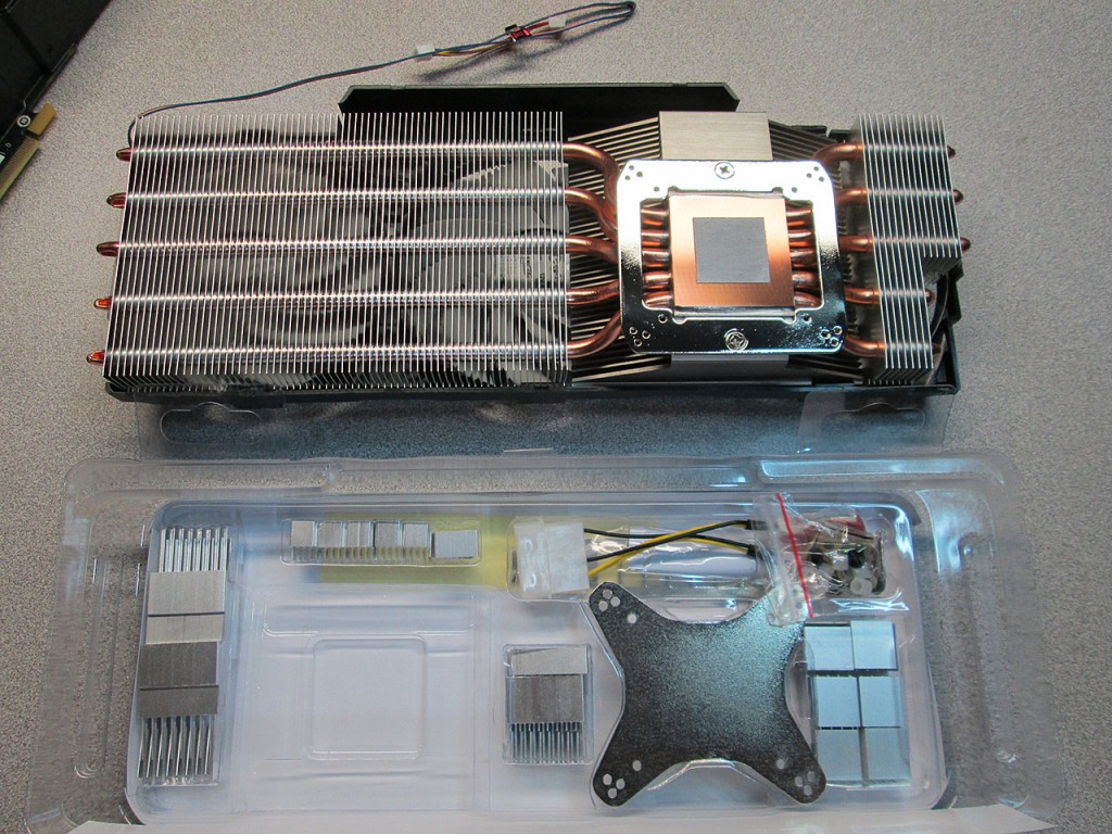
Last time I was shopping at Canada Computers, I came across an after market VGA cooler called the Accelero Xtreme III. I figured this would be a good chance to silence the video card. Unfortunately I could not figure out based on Google search if this particular cooler will be compatible with my video card. The cooler officially supports the GTX 680 reference board, but I took a gamble and decided to pick it up anyways.

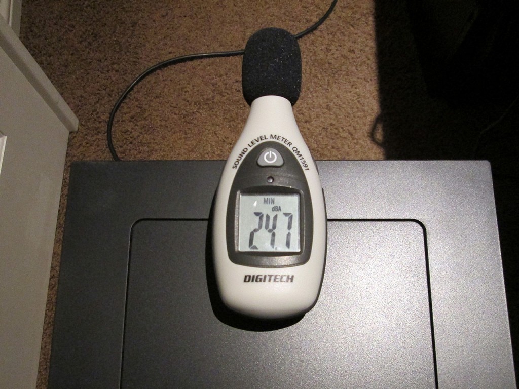
Before taking the computer apart, I ran a test measurement of the PC sound level. The measured sound level was 24.7 dBA right at the back of the case.

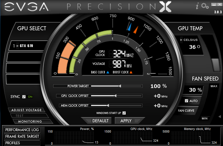
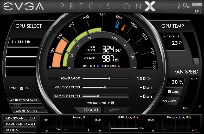
Also took a temperature reading of the video card with the stock cooler at idle. EVGA Precision software reports 36C with the ambient room temperature at 22C.

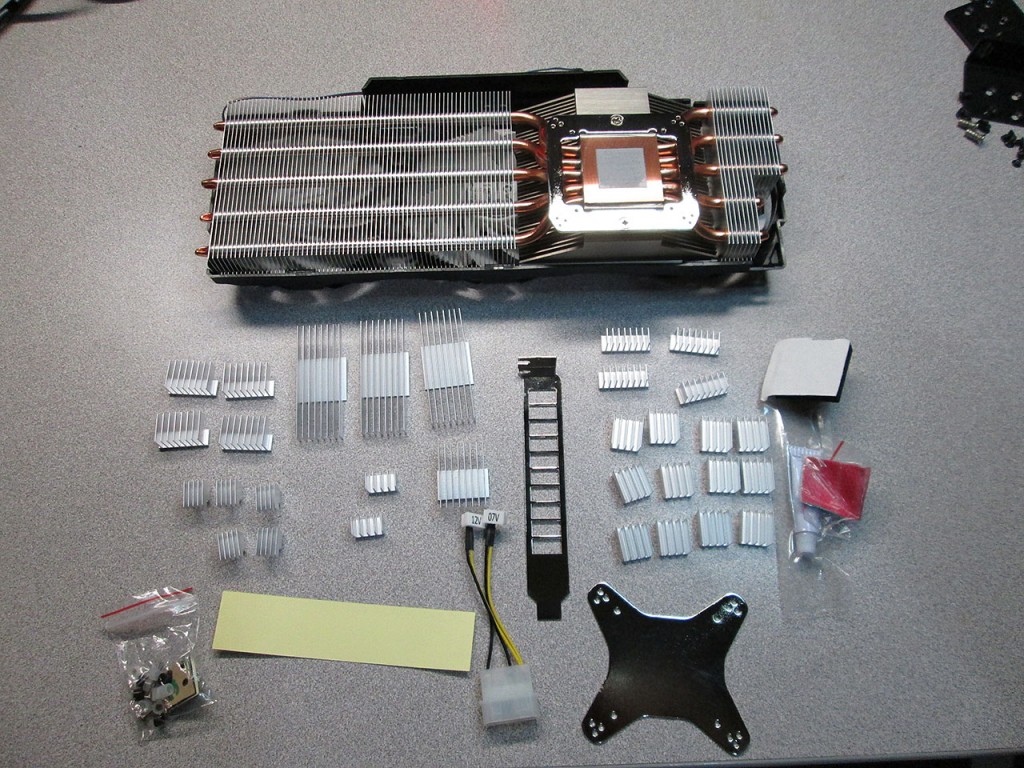
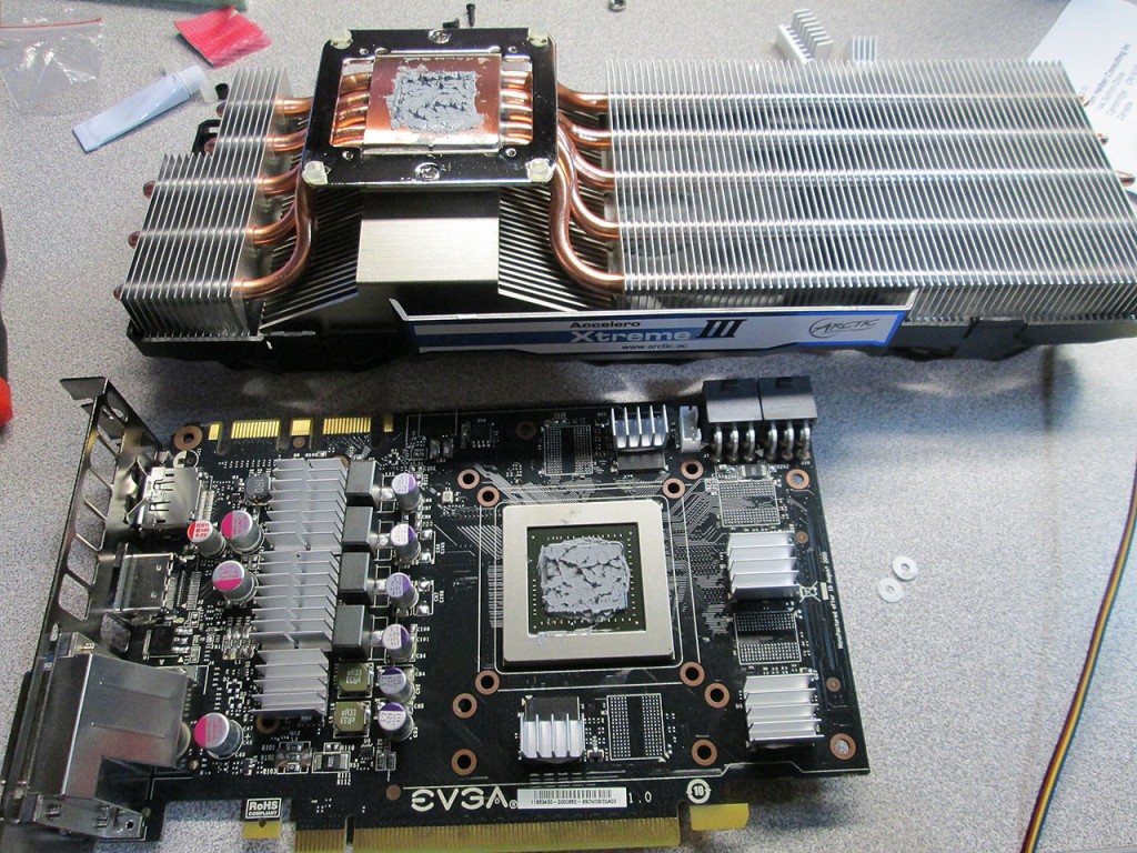
Time to start hacking at the video card. The Accelero package contains A LOT of small heatsinks. It’s possible to cool pretty much every component on the card if someone so desired. I assume all the heatsinks were provided due to the fact that this kit supports quite a variety of video cards. The odds of getting my GTX 470 working with this kit were getting better.

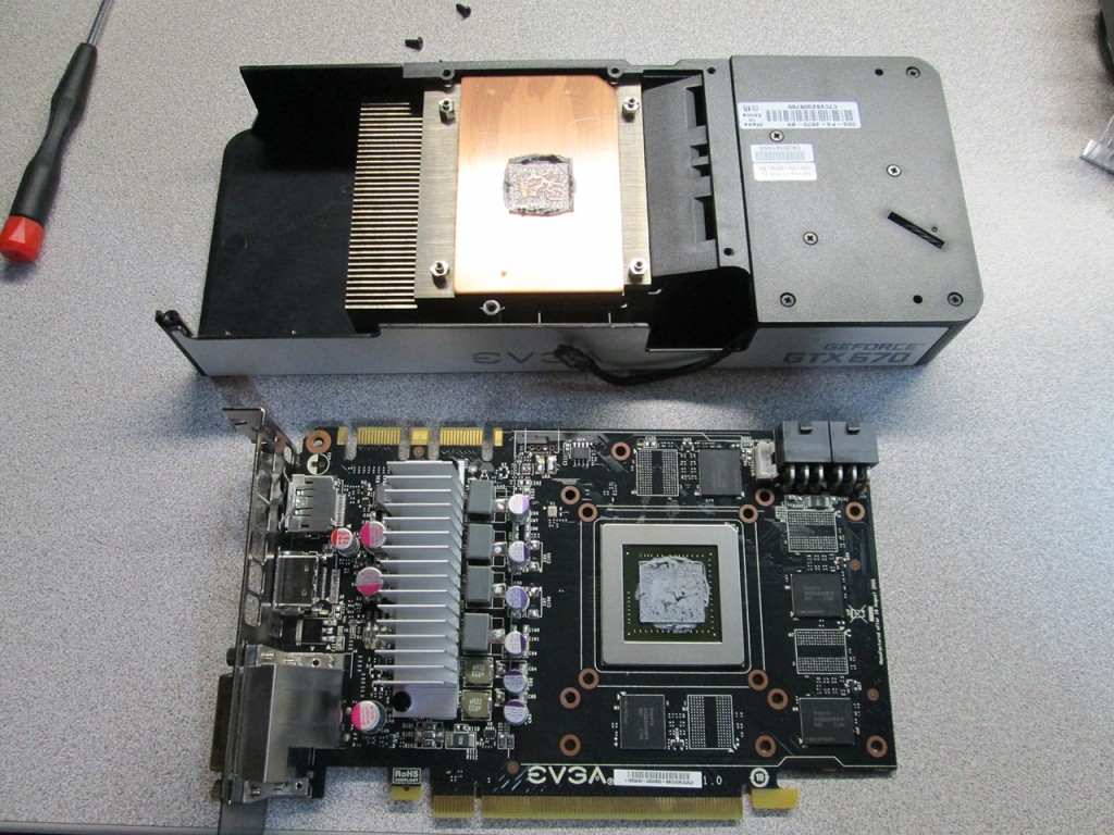
First step was to remove the stock cooler from the card. I never noticed that the card is quite a bit smaller than the cooling shroud.

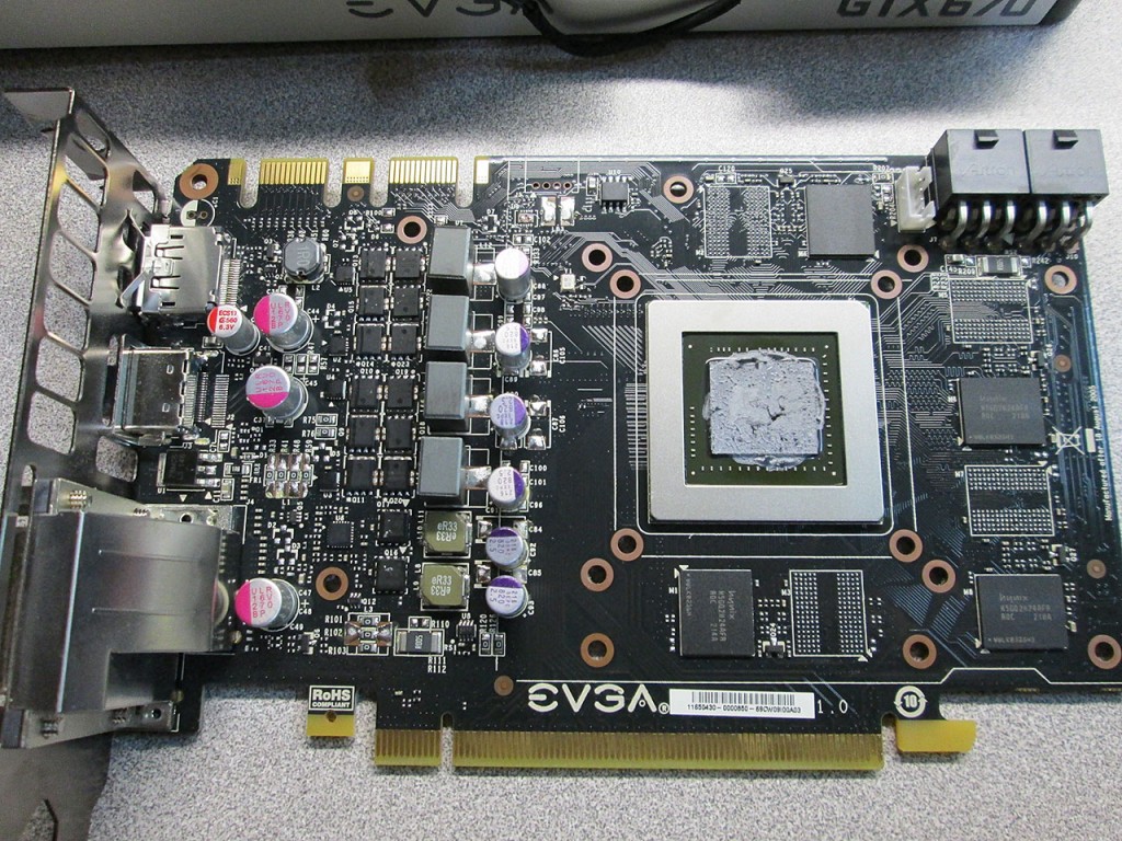
Removed the secondary heatsink exposing the voltage regulators. The stock VRM heatsink is rather large, having doubts if the much smaller individual heatsinks will be sufficient to cool the card. The VRM chips are quite small and densely packed, not a lot of room for heatsinks in the layout of the PCB.

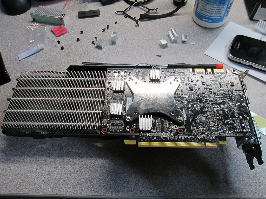
Did a bit of test fitting to see if the small heatsinks and the main one will not interfere with each other. Took a few tries and few combinations of heatsinks to get a good, even coverage of all parts. Even though the stock board didn’t cool the RAM chips, I decided to use up some of the heatsinks and put them on there too.

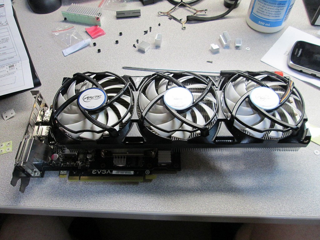
The fan/heatsink assembly mounted to the PCB. Definitely not quite perfect alignment, though it looks like it just might work. Looks like the EVGA layout moved the GPU a bit to the right which causes the heatsink to extend much farther past the card. Hopefully this contraption will still fit in the case.

Last step was to tighten the screws on the backing plate and install more heatsinks on the RAM chips.

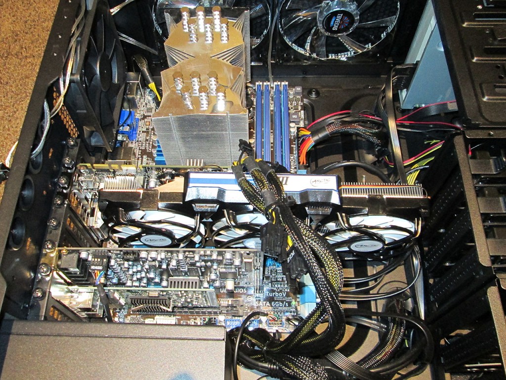
The frankenstein card just barely fits into the case. Pretty sure this would not fit in the original Centurion case I started with.

First thing first, fire up EVGA Precision X to see if the heatsink is properly cooling the components. Was pleasantly surprised to see a pretty significant temperature drop on the GPU. Even after few hours the temperature never went above 25C.

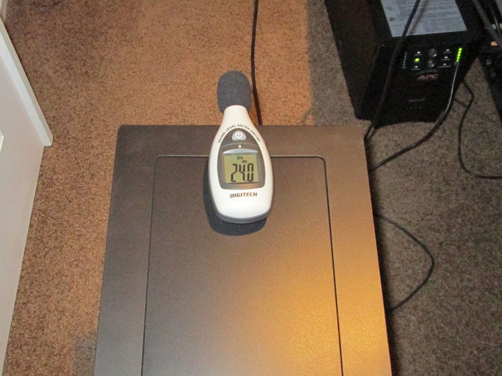
And of course the all important noise level test. The nose dropped somewhat from 24.7 dBA to 24.0 dBA. Not a significant drop as I was hoping to get closer to perfect silence.

While the computer is very quiet and definitely much quieter than I originally started, it’s still not quite there. Will continue searching for ways to silence it.

WatchGuard – pfSense – Tweaks

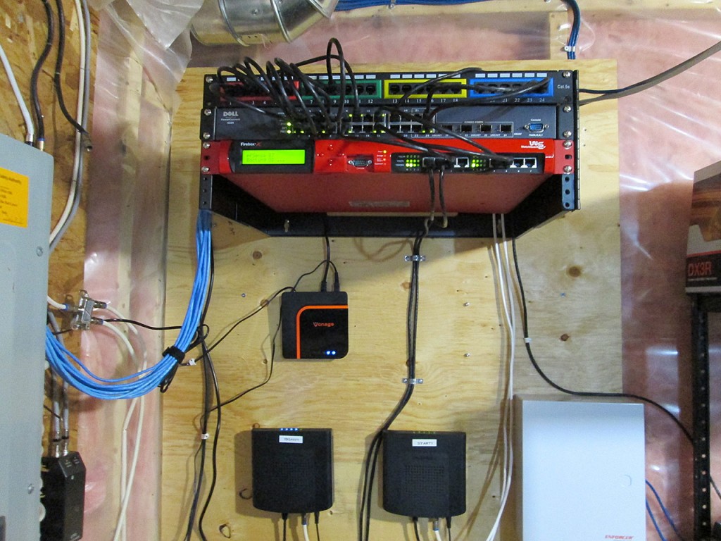
Continued work on improving pfSense running on my Watchguard x550e/x750e/x1250e firewalls. I got the x750e firewall nicely mounted at the utility board where my internet connections arrive at home.

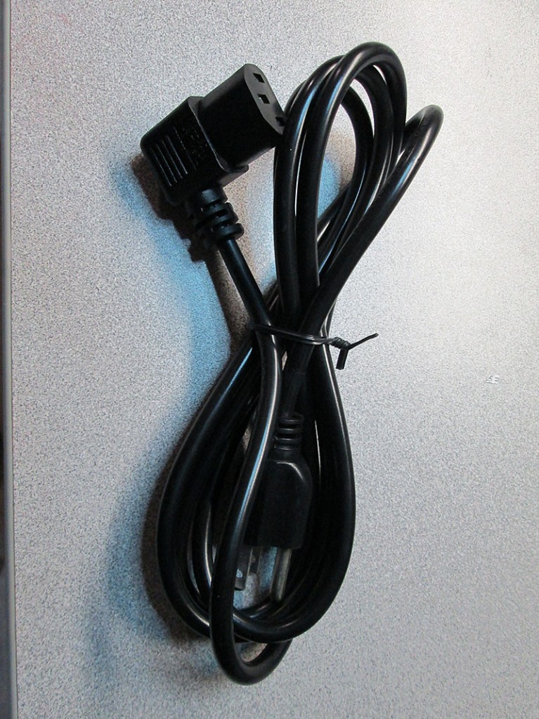
Though I ran into an issue mounting the firewall due to its depth. The standard bracket was not long enough to fit the firewall with the power cable protruding out the back. I ended up picking up a 90 degree cable that just made it fit.

Had the firewall running for a while now and during this time I’ve worked on it a bit more. There’s a known issue with the MSK interfaces timing out under pfSense 2.0. I’ve experienced MSK failure twice since installing 2.0. I’ve since upgraded to 2.1 Beta and so far it’s been stable. Was pretty happy about the fact that all I had to do to upgrade to 2.1 was to backup the config from 2.0 and simply restore it on 2.1 once I wrote out the new 2.1 image to the compact flash card.

In the meantime I also implemented a few more tweaks to all the firewalls.

Throttle down CPU
Enabled PowerD in System->Advanced->Miscellaneous. This however caused a flood of errors in the log and console when the system was attempting to throttle down the CPU.

kernel: timecounter TSC must not be in use when changing frequencies; change denied

This was easily fixed via a new tunable under System->Advanced->System Tunables.
Added a new tunable.
Tunnable Name: kern.timecounter.hardware
Value: i8254
Then rebooted the firewall.

Throttle Fans / Change Armed LED
Another great tweak was the Fan Throttle mod. The firewall is fairly loud with the fans running at 100%. This can be resolved thanks to the people on the pfSense forums. The program to control the Watchguard fans (and LED) is called WGXepc

Simply upload the file to the firewall. I used the File Manager package to upload the file to /tmp. One word of warning, by default the file system on the nanobsd build is set to read only. It has to be made writable by executing:

 
[2.1-BETA0][admin@aura.olympia.local]/tmp(4): /etc/rc.conf_mount_rw
[2.1-BETA0][admin@aura.olympia.local]/tmp(5):

One the file has been uploaded to /tmp

 
[2.1-BETA0][admin@aura.olympia.local]/(7): cd /tmp
[2.1-BETA0][admin@aura.olympia.local]/tmp(8): gunzip WGXepc.gz
[2.1-BETA0][admin@aura.olympia.local]/tmp(9): copy WGXepc /home
[2.1-BETA0][admin@aura.olympia.local]/tmp(10): cd /home
[2.1-BETA0][admin@aura.olympia.local]/home(11): chmod +x WGXepc

To add the automatic fan throttle to bootup process execute the following script. The value can be anywhere between 00 and FF (hex 0-255).

[2.1-BETA0][admin@aura.olympia.local]/home(12): echo "/home/WGXepc -f 30" >> /etc/rc.local

Lastly it would be nice to change the Armed LED to green when bootup is complete.

[2.1-BETA0][admin@aura.olympia.local]/home(13): echo "/home/WGXepc -l green" >> /etc/rc.local

Functional LCD
Also got the LCD working on the unit. This was actually quite simple simply install LCDProc and LCDproc-devel packages and configure as follows.

There is an issue currently with this as on reboot the processes do not correctly start in the proper order and cause the package to crash. The solution right now is to simply manually start the service once the firewall has completed booting.