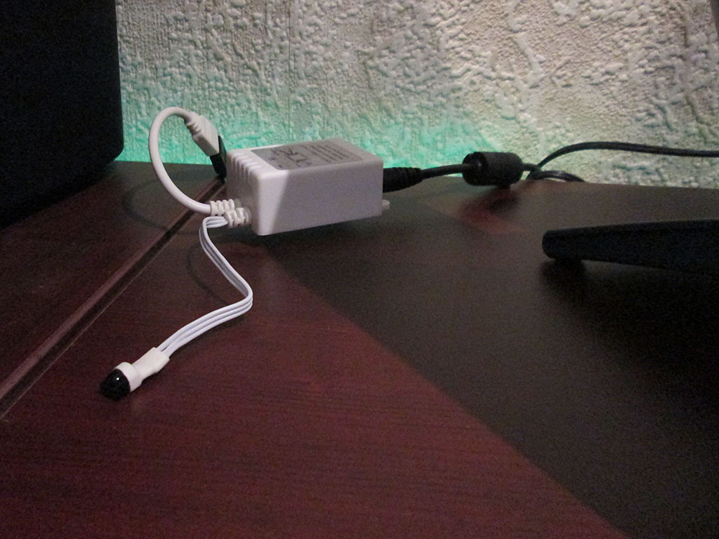
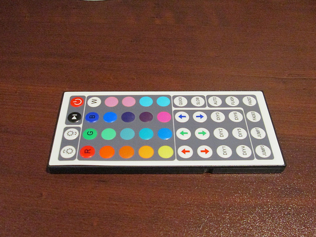
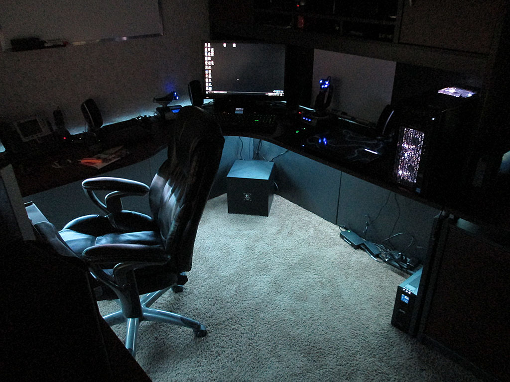
Few months ago I used some RGB LED lighting in my room (eBay China special). The setup uses an IR remote control and a control box to control the lighting. Power is supplied via a high current 12V power supply (10A supply)
My “gaming” computer uses green LED fans which looks kind of odd when using any other color on the strip. Changing the color of the computer required swapping the fans for a different color.
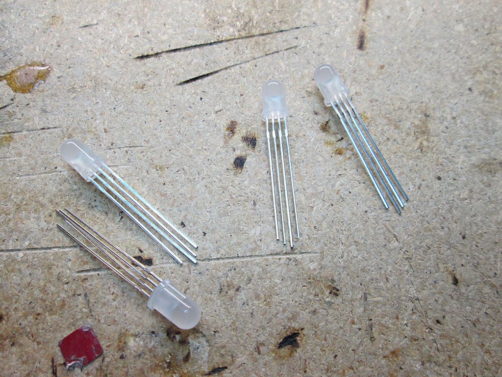
So, I decided to modify the fans to sync the colors of the fans with the rest of lighting. I already had tons of RGB LED’s, so it was really a matter of A LOT of soldering. One thing to note is that the LED ligthing system uses common Anode configuration, with a single 12V rail and 3 (RGB) grounds.
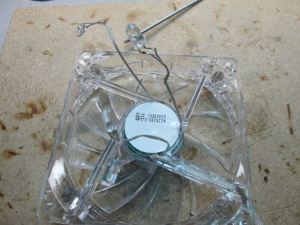
Once I pulled the fans from the computer, I had to remove the old green LEDs from the fan.
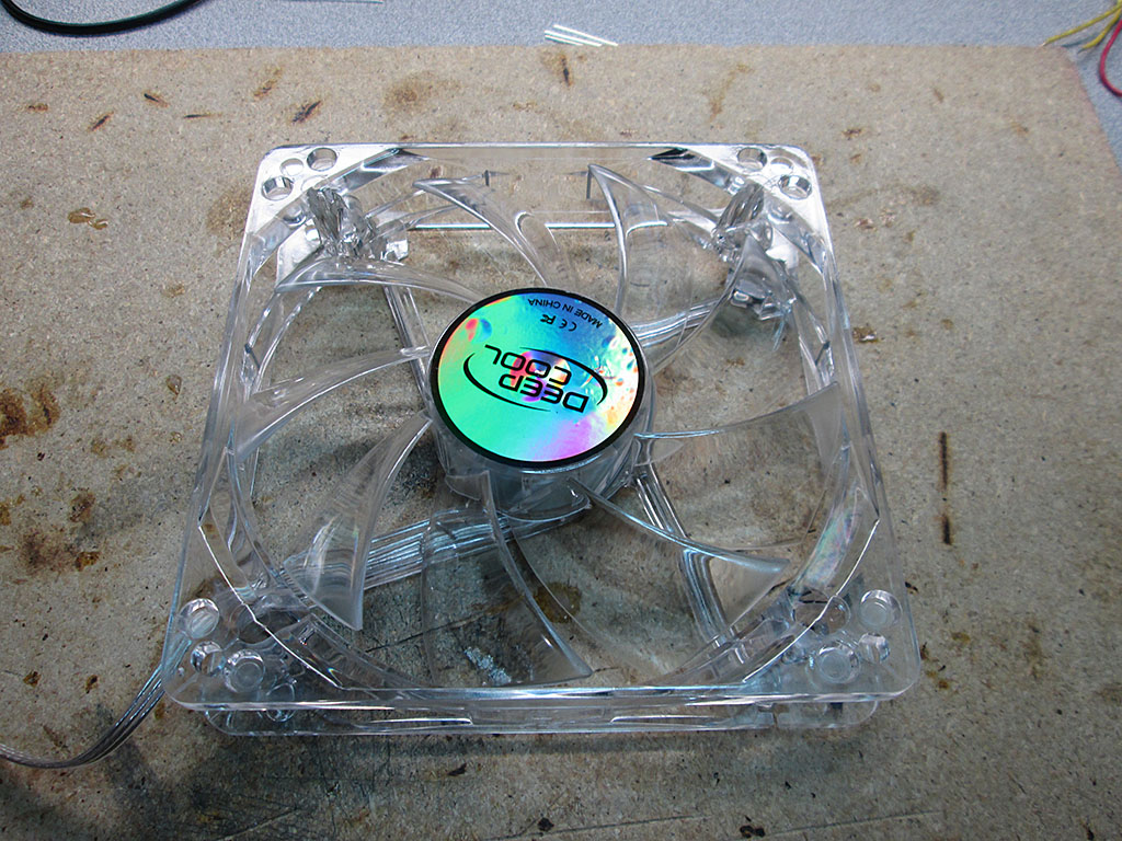
Fortunately the LEDs are simply pressed into place and not glued. This makes them easy to pop out with just a little bit of force.
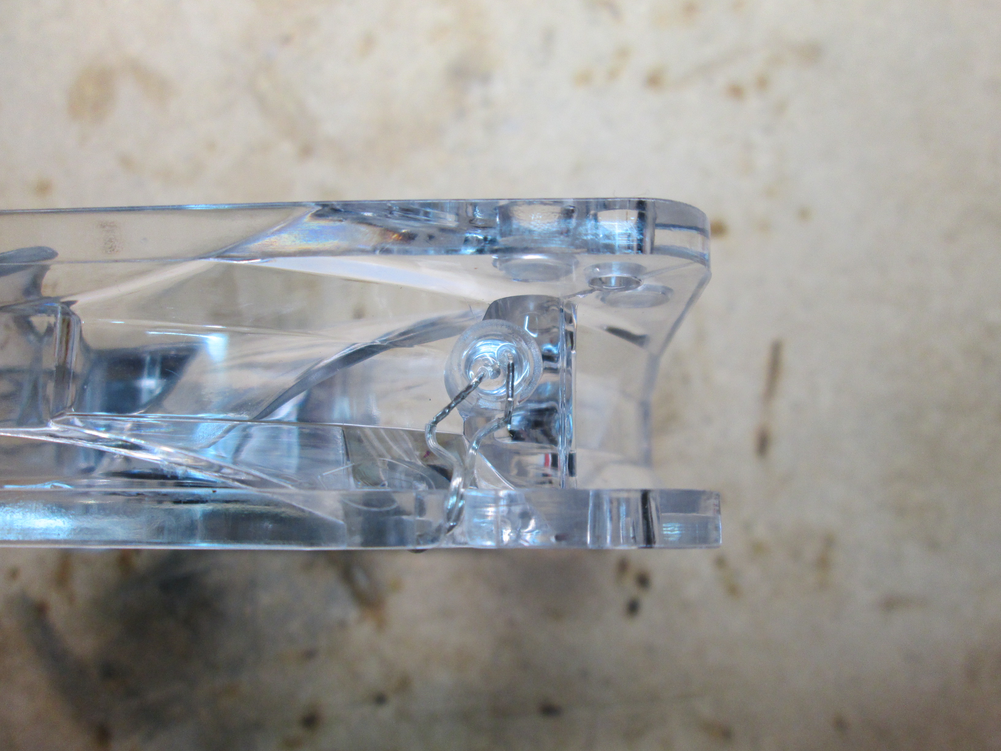
The leads for the fans are connected to a small circuit board underneath the sticker on the fan
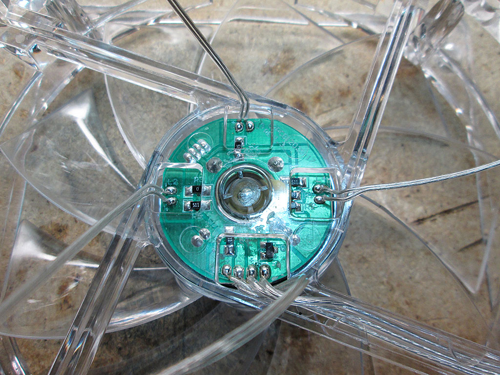
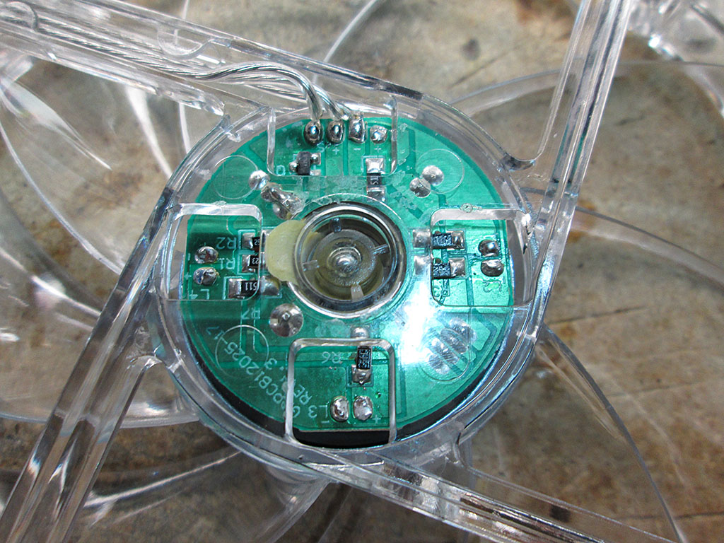
A quick application of a soldering iron and all the LED leads have been removed. Since the LEDs are no longer supplied with fan voltage rail, the brightness of the LEDs will no longer be tied to the speed of the fans.
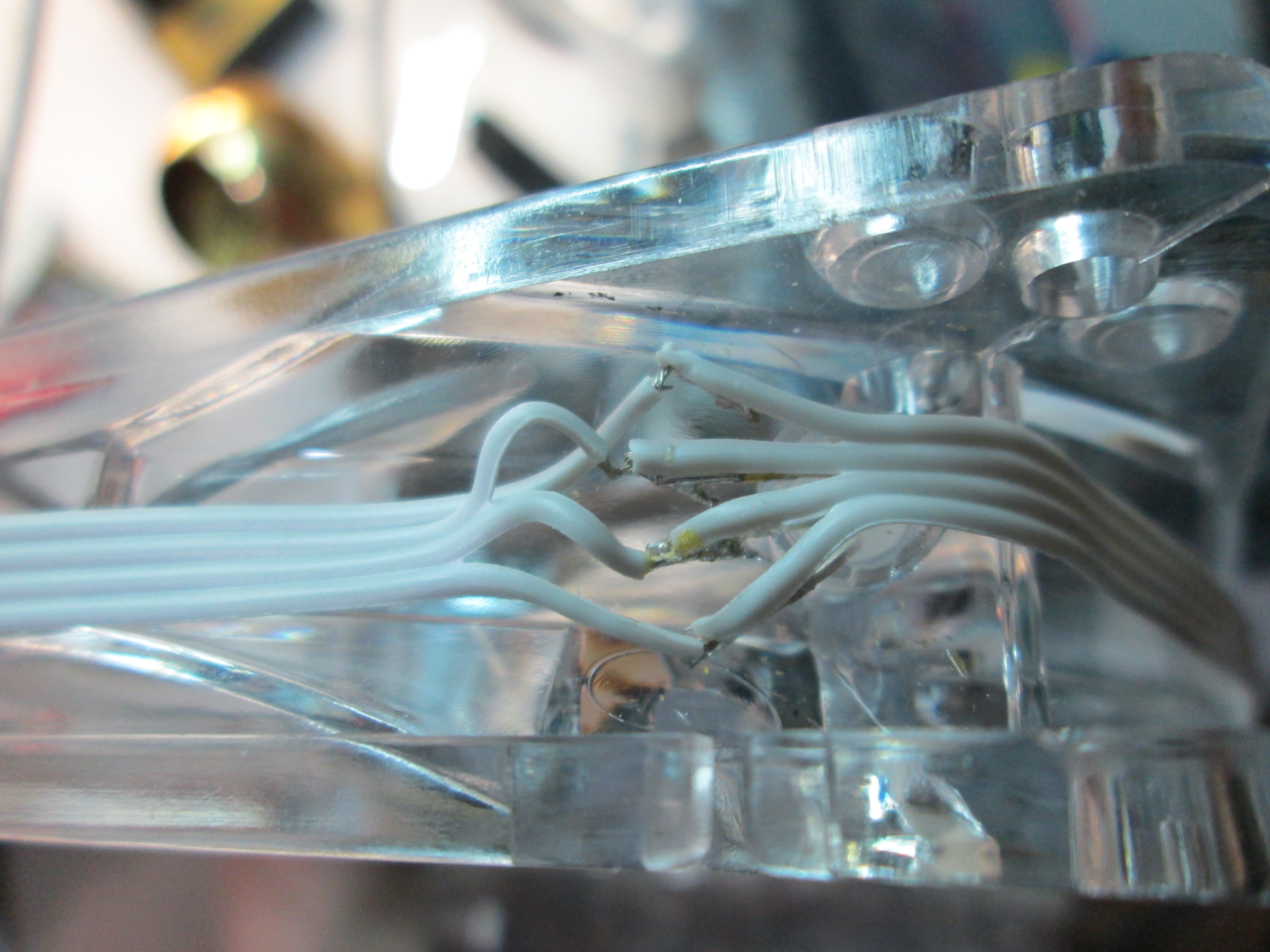
The RGB leds a just tiny bit larger than the original LEDs so it took a bit of extra force to press them into the socket.
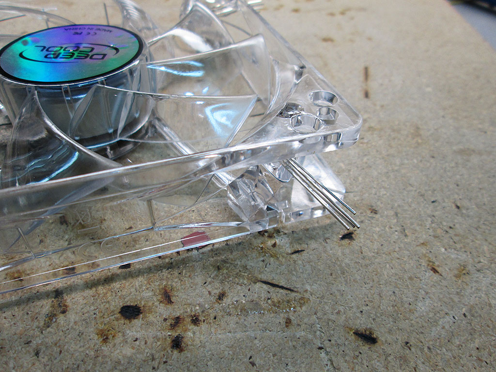
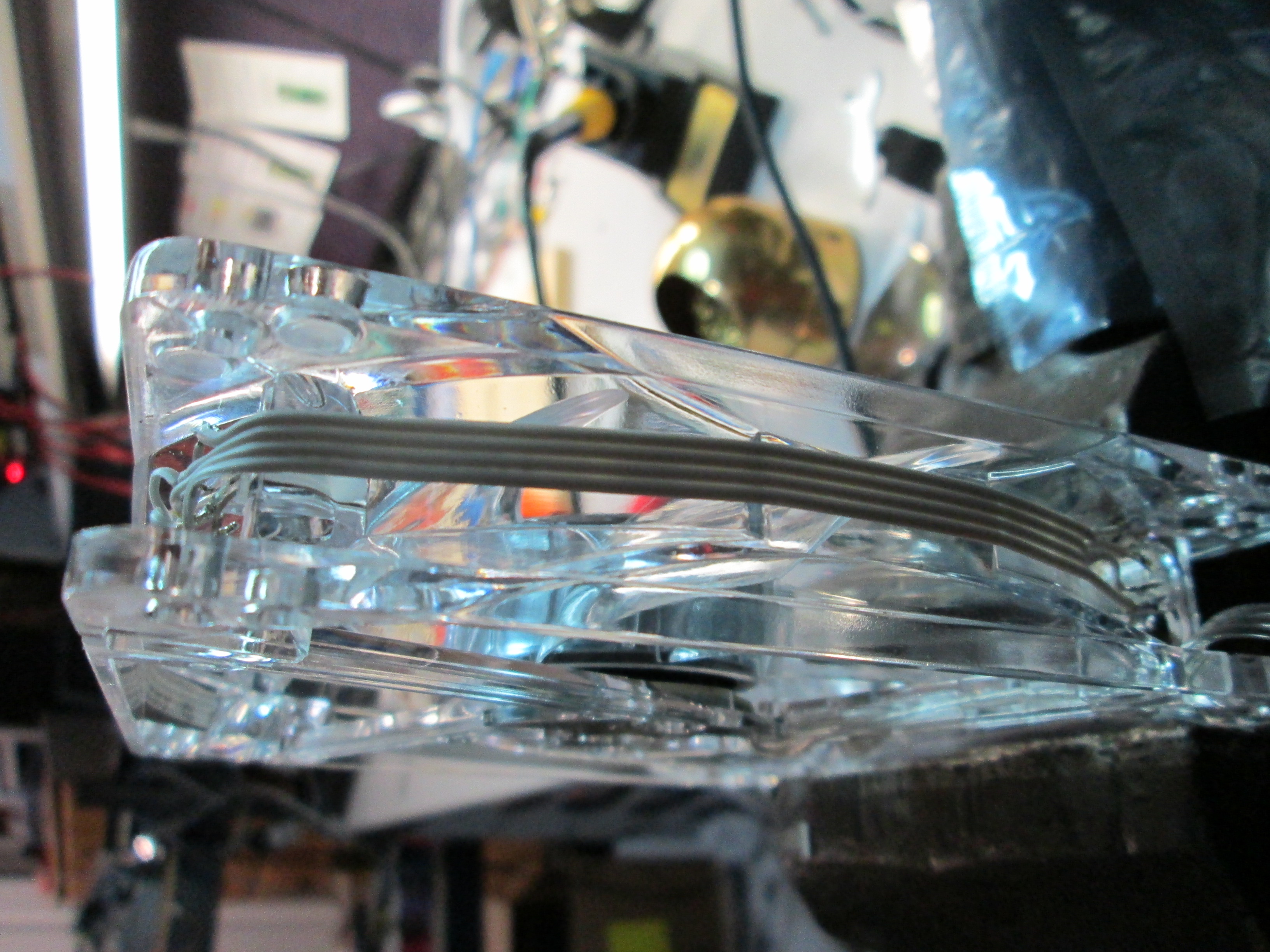
I used standard ribbon cable to carry the RGB voltages across the LEDs in the fan. The individual current for each fan is very low so the ribbon cable can easily handle the load.
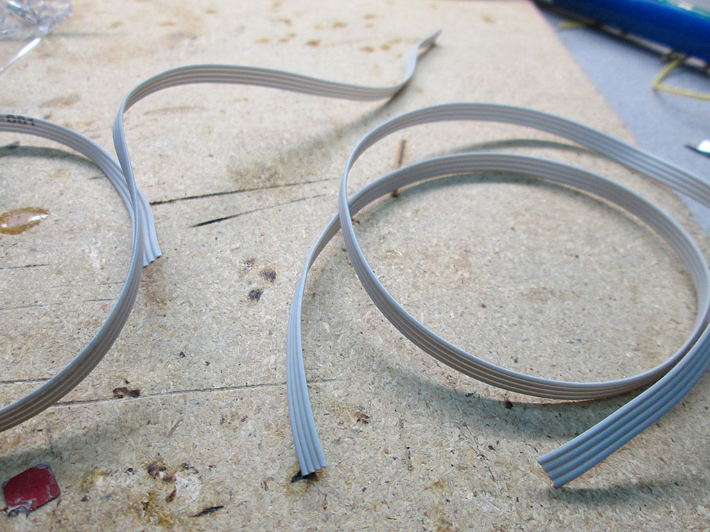
All LEDs were connected via point-to-point connections. This was actually a fair bit of work. The ribbon cable is quite delicate so I had to take extra care when stripping the wire ends as not to cut the lead.

The ribbon cable is nice and flat so it doesn’t affect the overall diameter of the fan much. Still, there would be certain configuration where the fans are too close to an edge where this would be problematic. Fortunately in my case, the fans are spaced sufficiently apart that the ribbon cable doesn’t interfere.
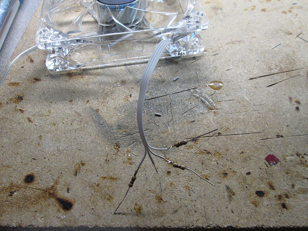
Once all the LEDs were electrically connected they had to be terminated via current limiting resistors. During bench testing I found that the 470ohm resistors provided the best brightness to current ratio at 12V. Since the LED receives power on a common Anode and each color draws slightly different amount of current, it’s important to place the resistors on the individual color leads. Putting the resistor on the anode pin will not work properly when using more than one color at a time.
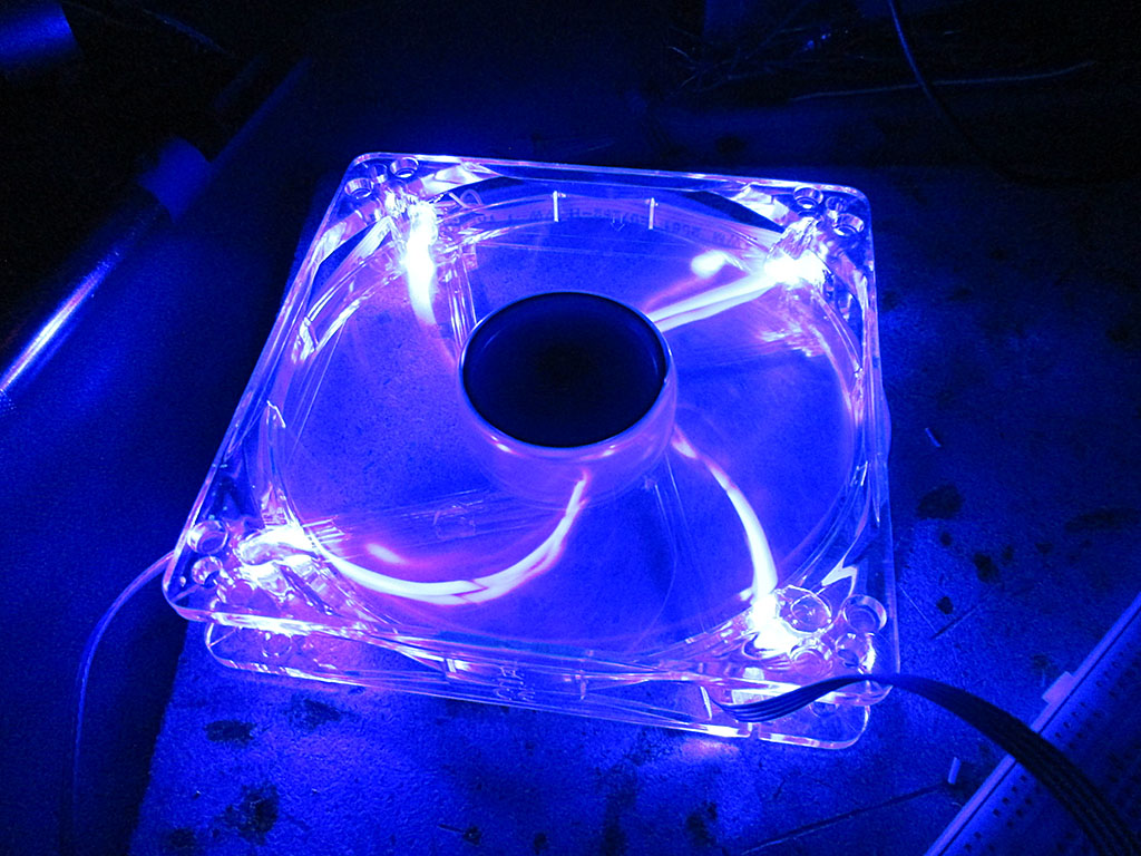
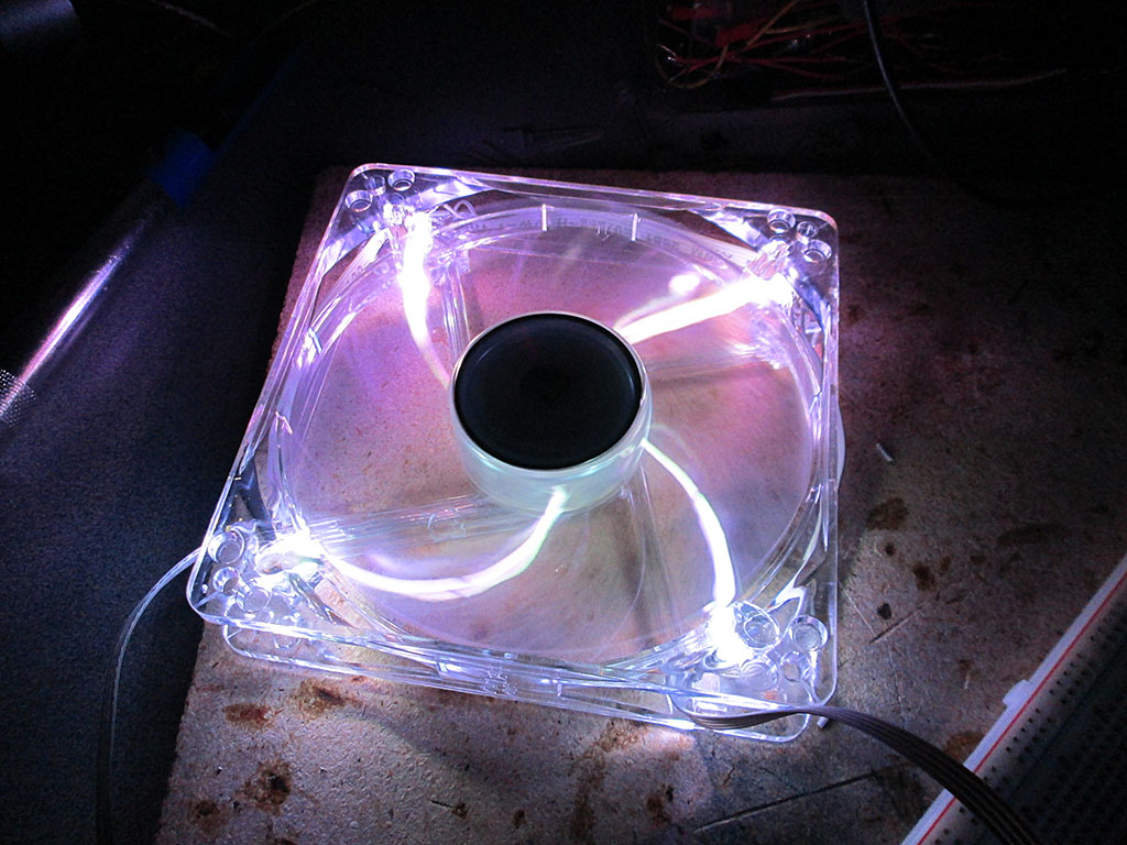
With the first fan completed I did some testing to see how the setup will stack up. I wasn’t sure if the RGB LEDs will be bright enough.
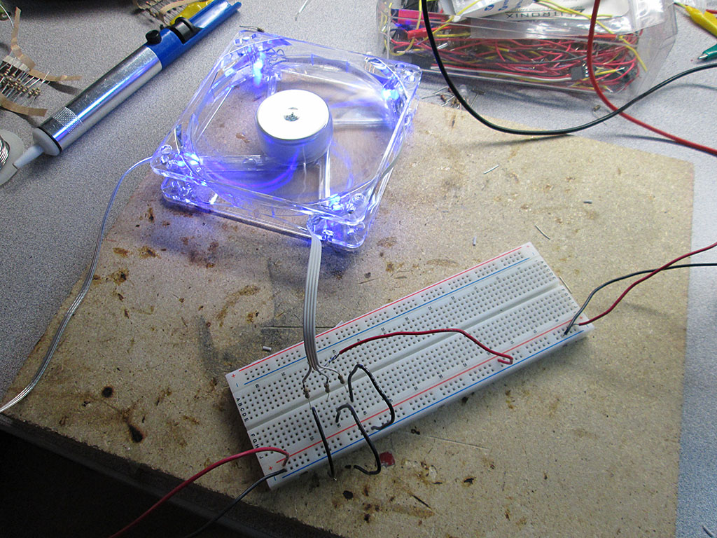
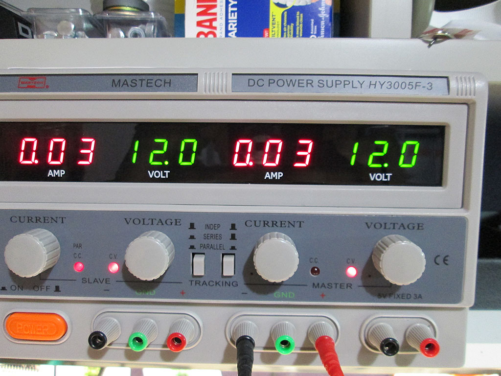
At 12V the individual colors only draw about 30mA per fan.
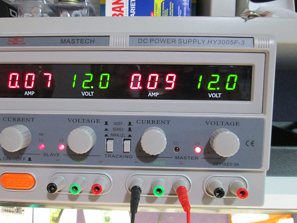
With all the colors lit, the draw was just 90mA. Which works out to under 500mA for the whole computer. A negligible load on the control box for the ambient lighting.
To connect the fans to the LED strip I bought some JST 4 pin connectors. It’s surprisingly difficult to find small 4 pin connectors locally, so I had to do another China eBay order and wait another month for them to show up.
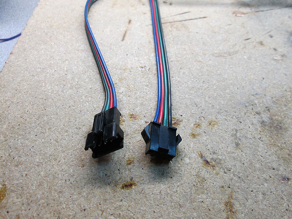
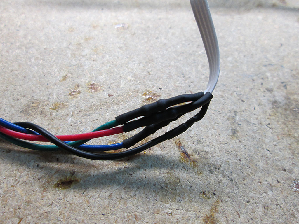
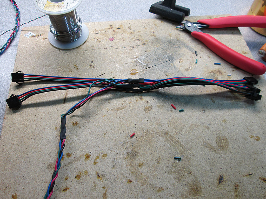
To complete the connection, all the resistors were then wrapped via heatshrink and soldered to the connectors. I gave each fan about 8″ of wire to make the connections between the fans easy.
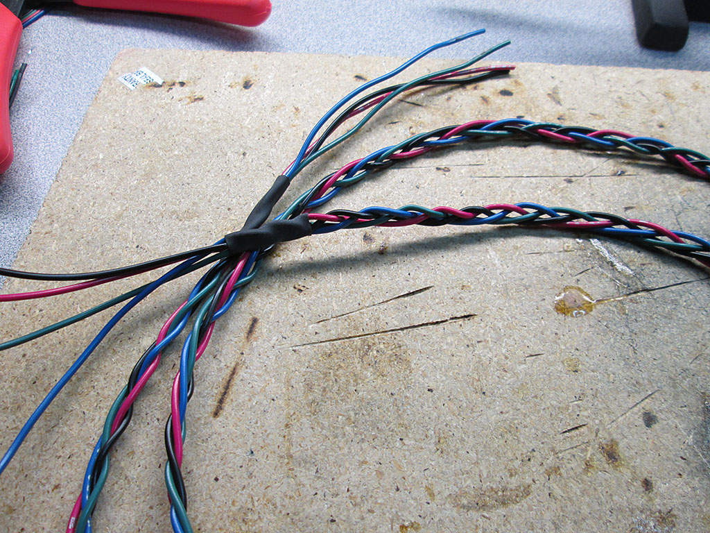
To connect all the fans together and to connect them to the LED strip I braided few 24 gauge wires to make a nice flat cable. This cable will run outside of the computer via a hole (meant for water cooling hose) in the computer case.
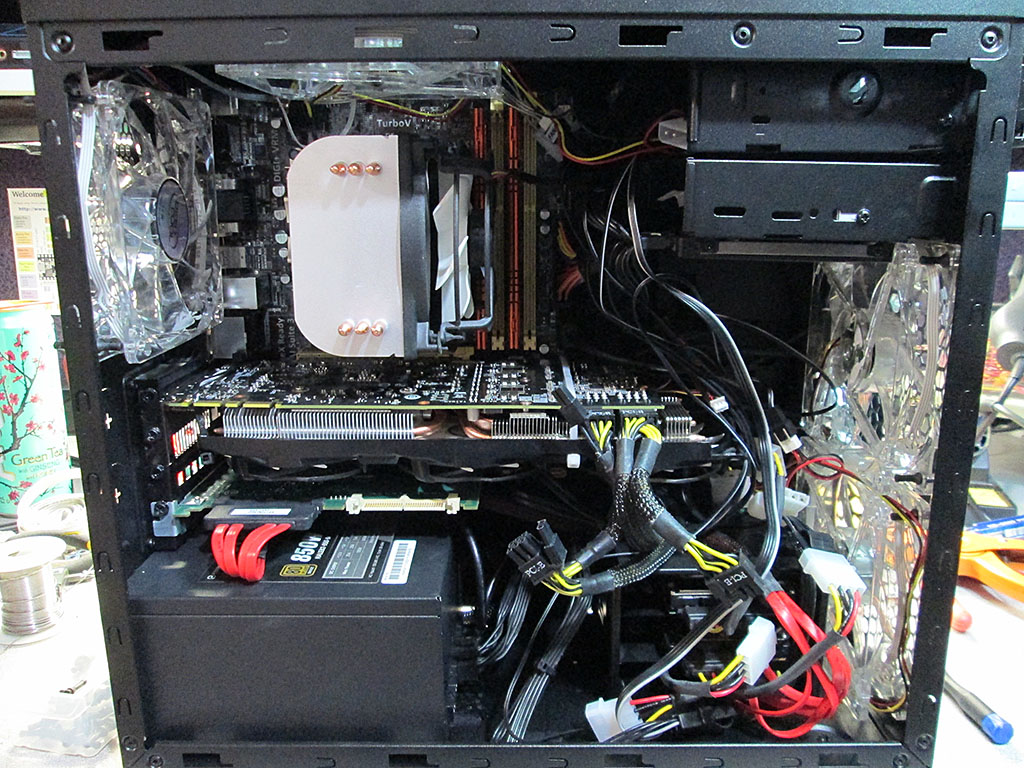
Once all the fans were soldered up, I installed them back into the computer. My wire organization skills are certainly not the best, but then again this is just a Mini ATX case so not heck a lot of room to stash the cabling.
Last step was to connect the supply cable to the LED strip and turn it all on.
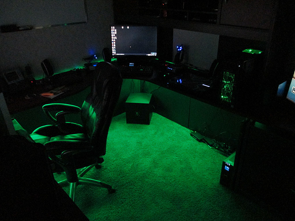
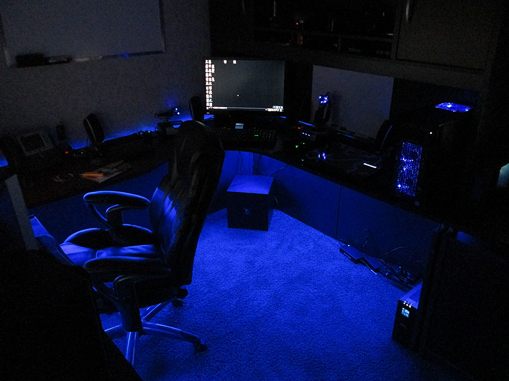
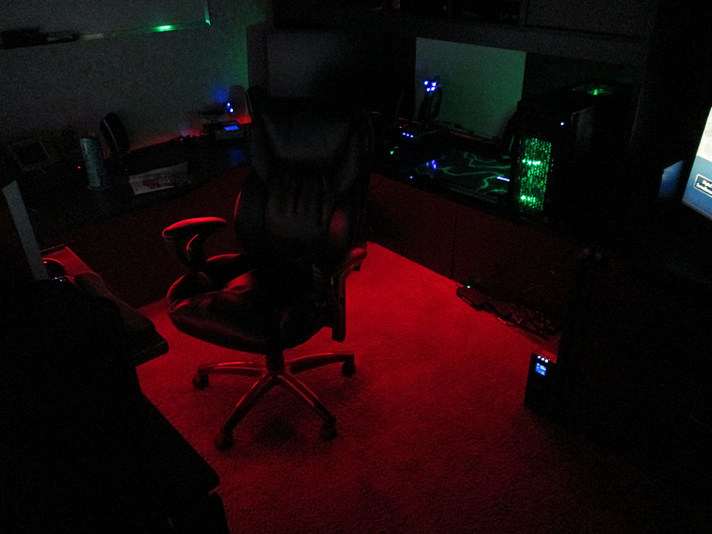
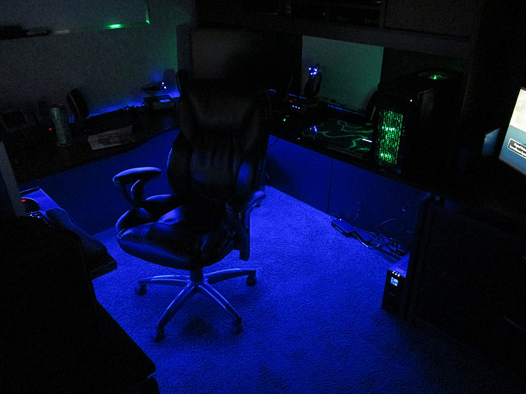
Here’s a short video of the LED system, with the light mode set to cycle all colors.