After having some phantom issues with my carputer last year, I’ve decided to rebuild from scratch.
This time I wanted to troubleshoot all issues on the bench before loading it into the car.
Goals:
– Standard features: Audio/Video/Nav
– Analog Gauges with Alerts (from Analog Inputs)
– DashCam
– Clean OEM Like Install
– WiFi/3G
– Control N2MB WOT Box
– Trinity Data Logging
So rewind back to last year. My first attempt at the carputer was not great, but it was a good learning experience.
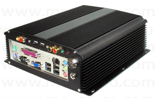
I purchased a ready to go CarPC:
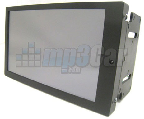
A 7″ Lilliput Screen:
Plus some other parts: Power Blocks, Wiring, PAC-Audio CAN Converter.
After some minimal planning, I started the install.
I ran the required wires (Audio, USB, VGA) plus some additional wires for future use (5V, 12V Switched and 12V Constant)
I carpetted some 1/4 Ply and Ended up with this
I had a low volume issue so I purchsed a Pre-Amp and added it to the board.
The system ran OK. Though i had freezing issues and USB dropouts. Also (not pictured). The monitor wasn’t flush with the bezel as it was physically larger than what the bezel allowed.
Back to this year, I decided to tear it all apart and get it working properly. Additionally with some power mods coming I needed gauges. I didn’t want to do another pillar gauge setup, I also didn’t like the trinity mounted on the windshield so I elected to incorporate the gauges into the Carputer.
As a software developer it would be relatively easy to write software for it.
For analog to digital input I went with an Arduino board. It easy to write software for it and with its 10bit ADC it would give me enough resolution to use for gauges.
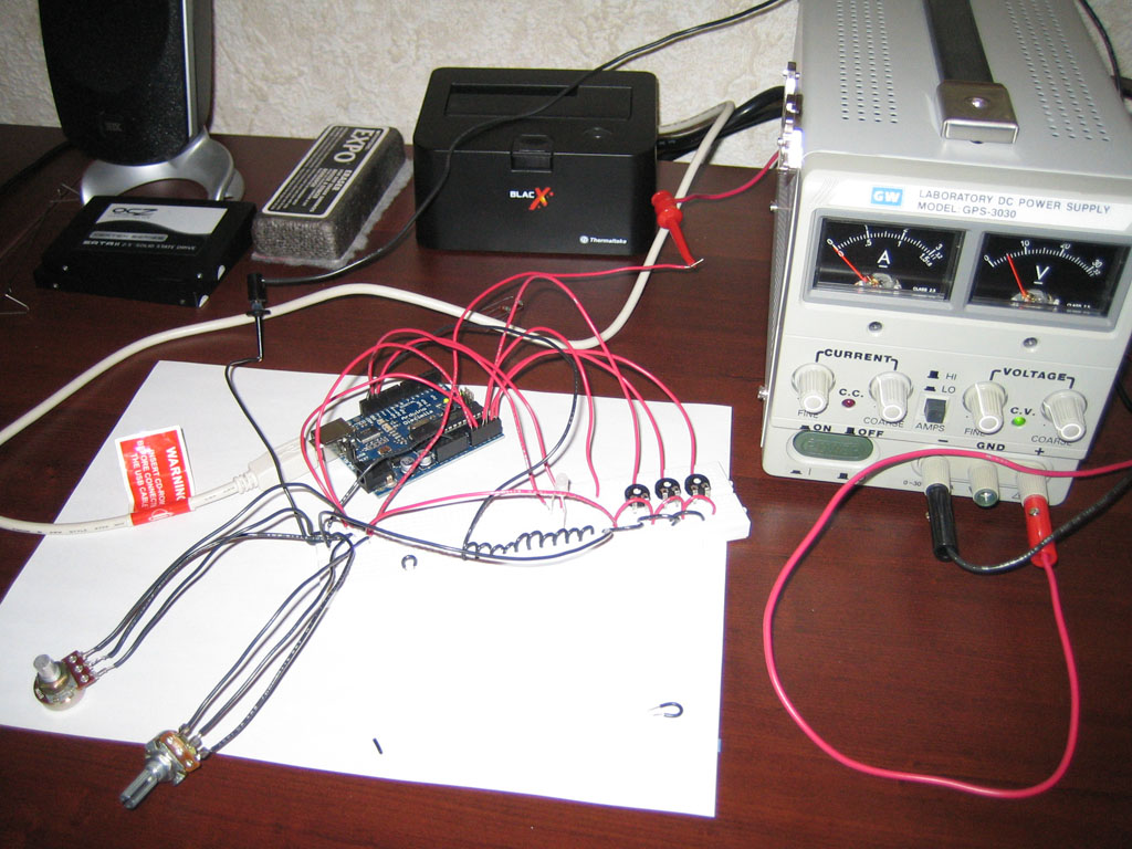
I’ve setup a simple simulation with a couple of “senders” to read input from and started coding.
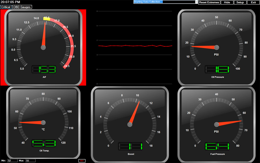
Couple of days later I ended up with this.
Couple of days after that I added Visual and Audible Alerts (Text to Speech and Sound File support). Couple of extra gauge designs.
I haven’t added OBD Support yet but it should be relatively easy talking to an ELM Controller. While I was still tweaking the software design I moved onto some fabrication.
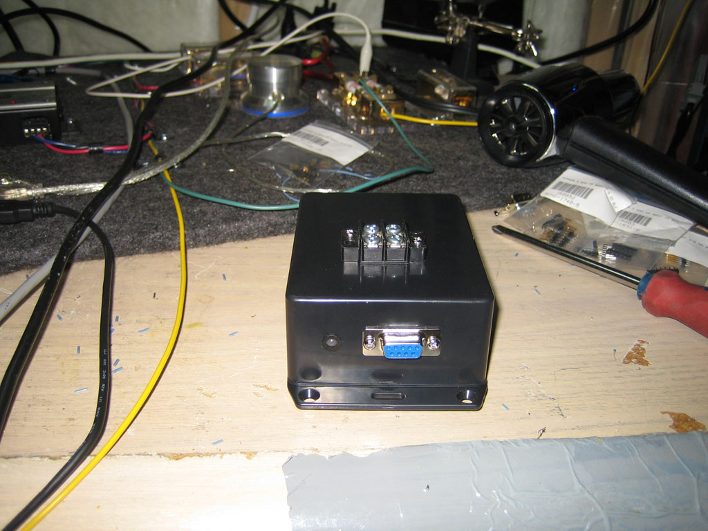
I needed an enclosure for the Adrduino so I built one.
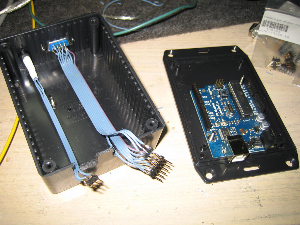
Input is brought in via a DB9 Connector (6 Analog Inputs, 3 Digital Inputs)
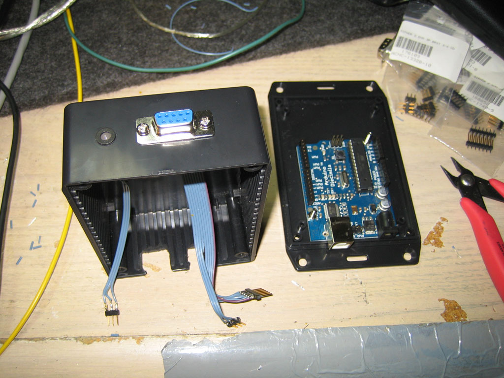
Activity LED and Ground Connections bring it all together. Arduino box is ready.
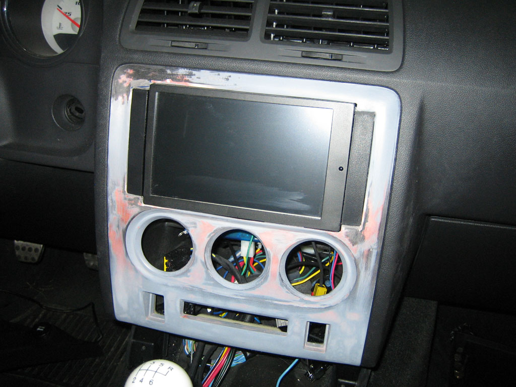
Next step was to modify the factory bezel to accept the monitor flush.
Strong Note: I’m not a fabricator, I have no patience or skill to create stuff like this so this process took a lot longer than it should have and turned out less than stellar.
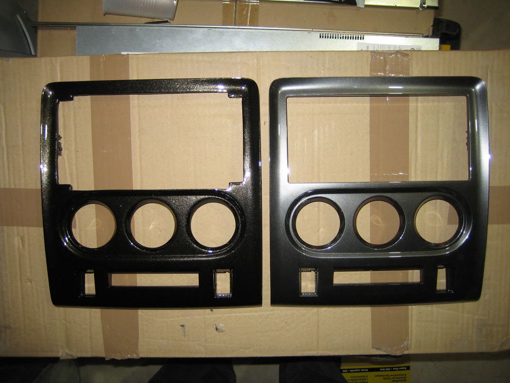
For comparison stock bezel and the one I’ve mangled. I’ve originally used bondo body filler but this idea backfired when the bondo started cracking
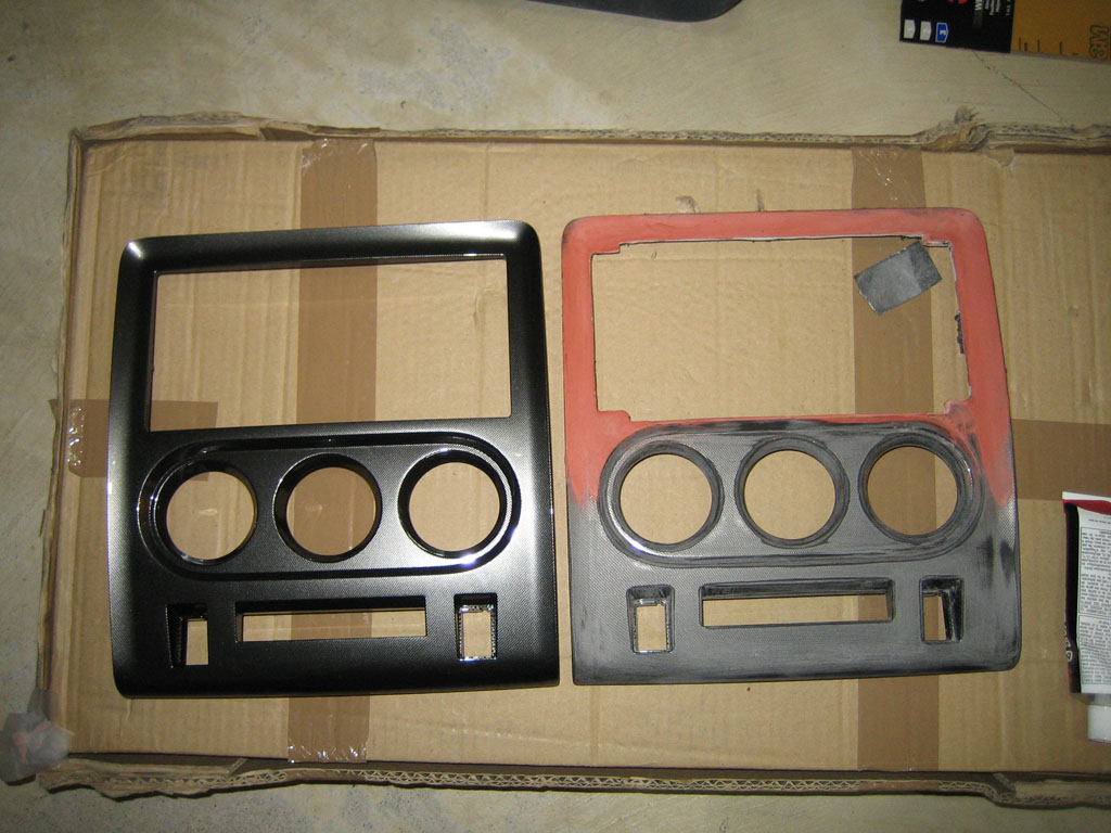
I’ve moved to bumper epoxy. Better than Bondo since it was more flexible. After a lot of sanding, filing and grinding I get this.
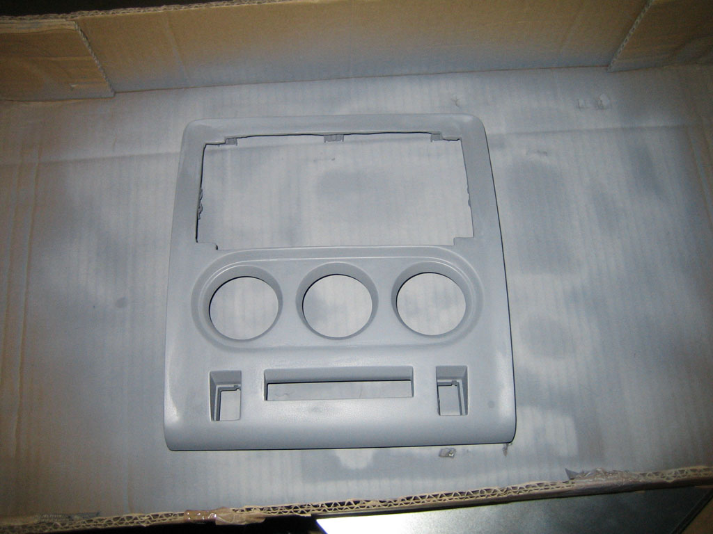
After was seemed like days of priming, spot bonding, sanding I finally threw in the towel and started on the finishing process
Used Automotive specle paint that resembles the Black Pearls of the Challenger.
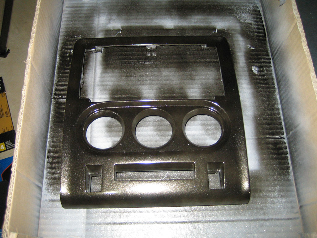
Couple of coats of clear and we have a finished bezel. Once again next to the original one.
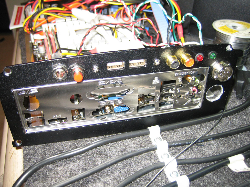
So while the paint cures. Onto the next step. Modify the Carputer a bit. I wanted ability to reset the computer from within the driver seat in case it did froze again, and while at it show status indicators (Power, HDD Activity).
I migrated the LCD Power supply next to the original reset switch and added a 4 Pin Connector for the Reset Button and the Two LEDs
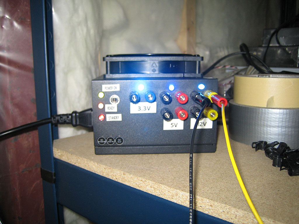
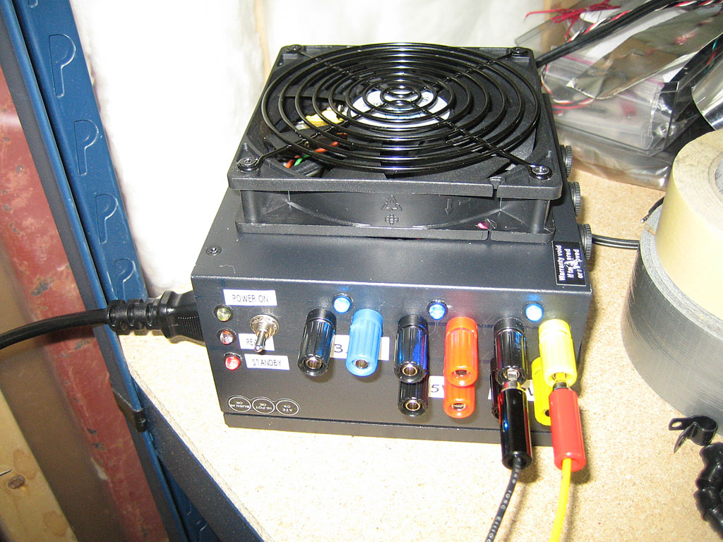
I needed a bench power supply that can run everything off of 12V and have sufficient power to handle medium to high load. What better than to convert a Computer Power supply
I’ve purchased a power supply with a single 12V high output rail. This power supply can deliver 35A at 12V. I’ve added individual rail fuses, stand-by switch and probably too many LEDs
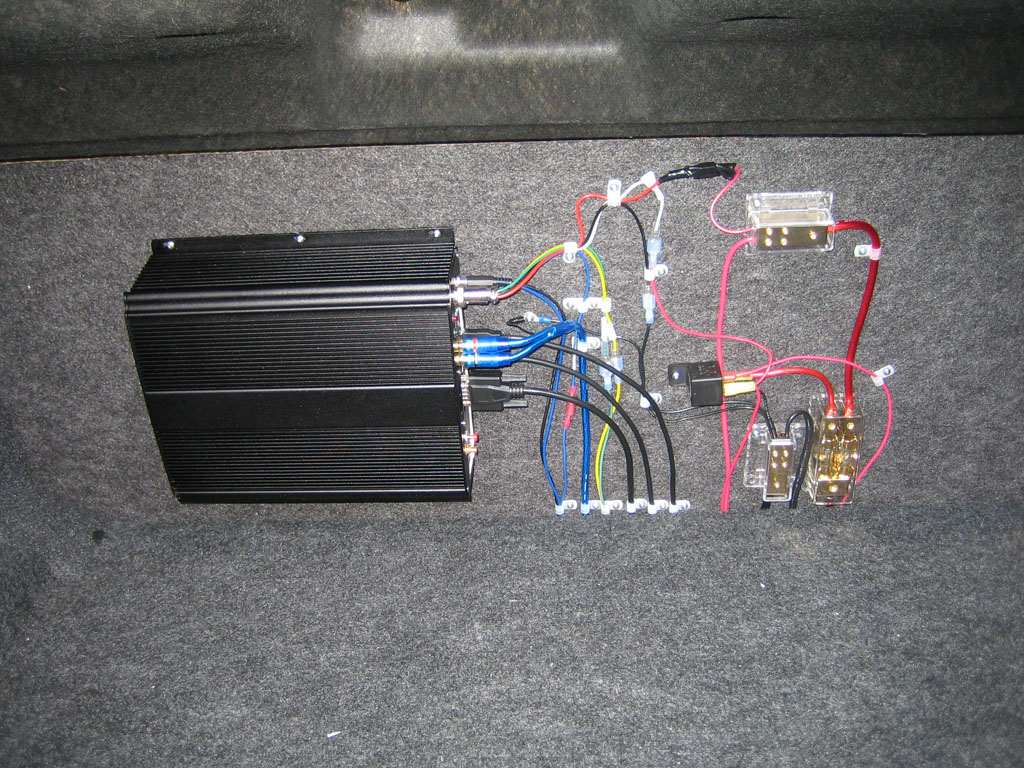
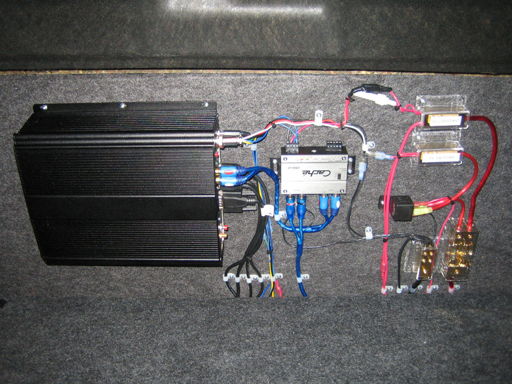
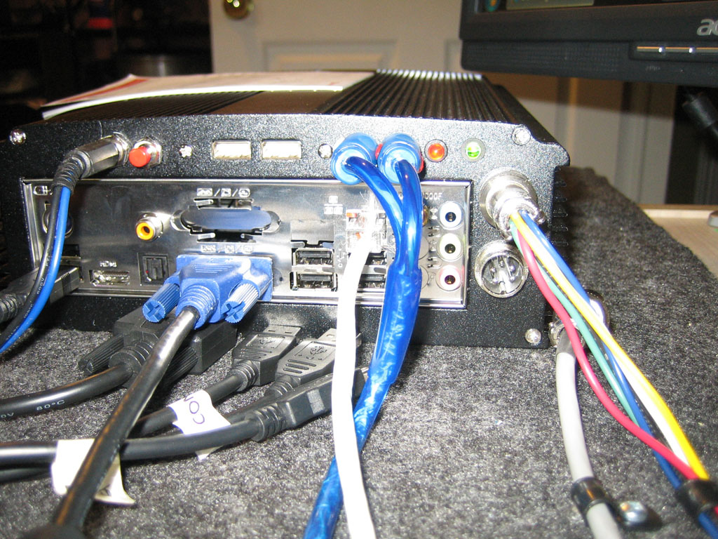
Once I got the supply issue resolved I laid out the carputer system and wired it all together. I wanted to keep the audio, USB and Power cables separate to keep noise to a minimum.
I also drilled vent holes in the top of the carputer case. The new Zotac ION board was running hotter than the Intel board the Carputer originally came with.
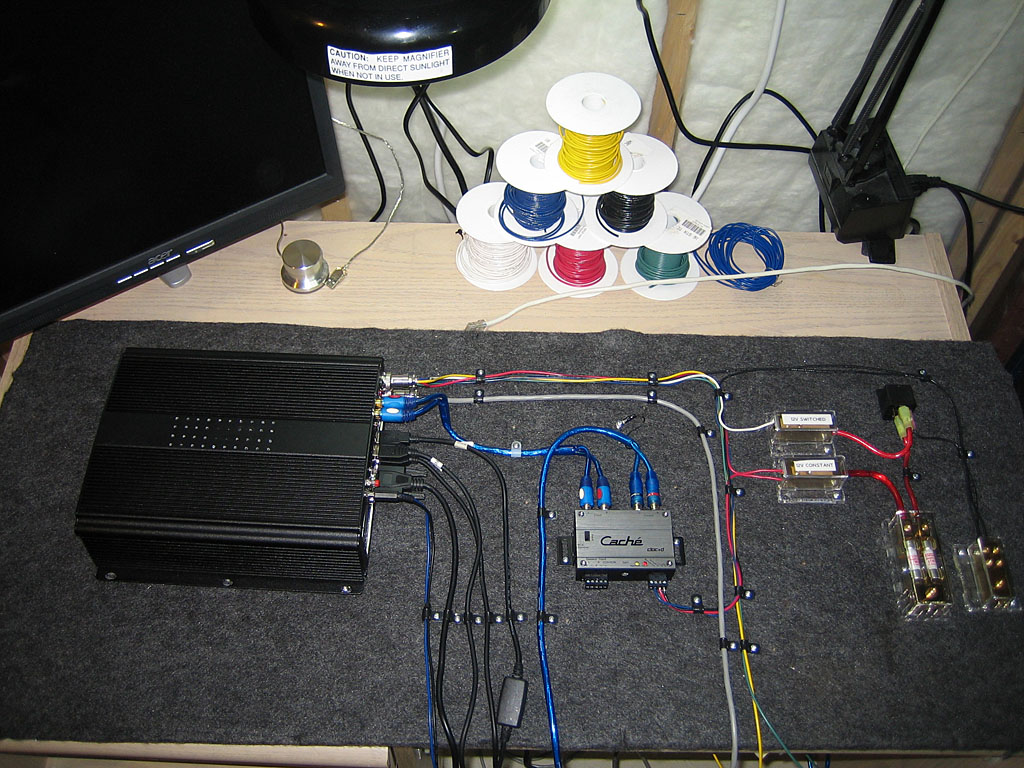
And that’s where I’m at right now. Next step is to get some Heavy Duty 10′ USB cables and complete building the mockup.
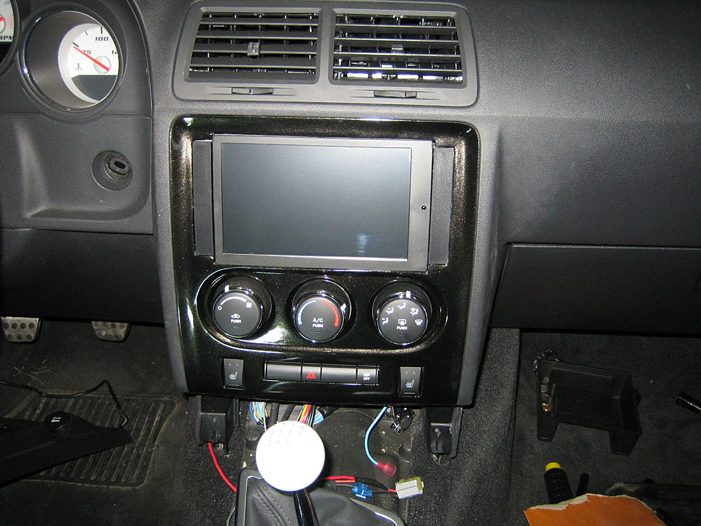
Update [2011-03-12]
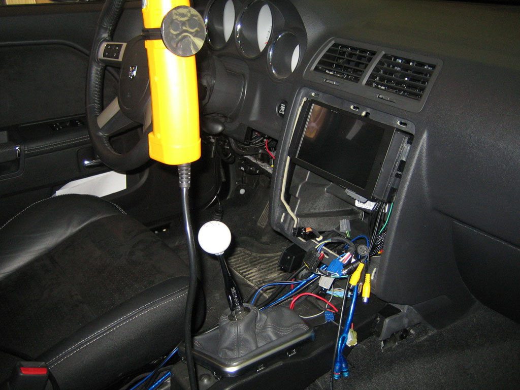
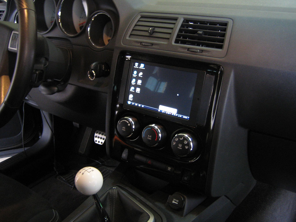
Installed the bezel today. It’s not great but it’ll have to do for now. The harsh flash light makes it look worse than it is.
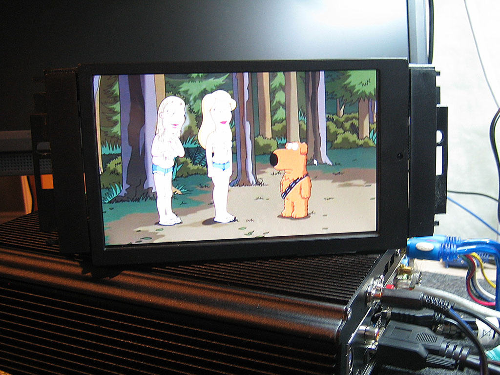
I’ve installed and configured CentraFuse today. Easy stuff.
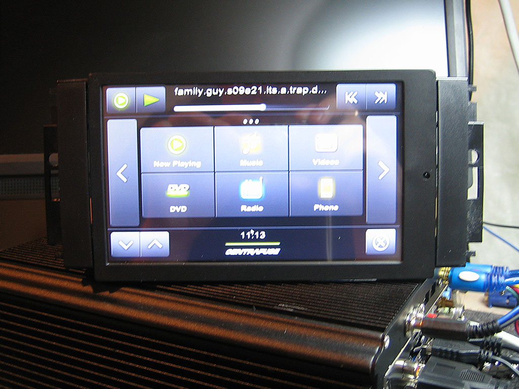
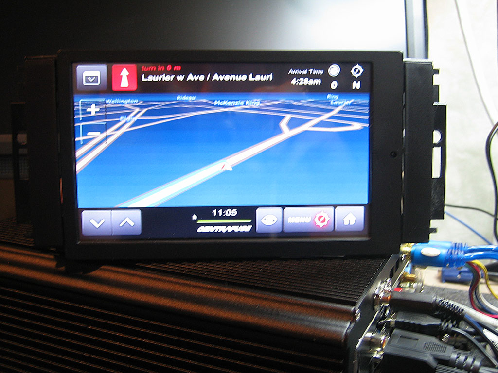
Not sure about the built-in Nav. It’s using Navteq 2009 maps. I still have Garmin PC software as backup so we’ll see.
OBD Update: I have sucessfully communicated with the OBD2 Interface. Wrote short code to scan all Mode 1 PIDS and see which ones return data. Good news that a good chunk of usable PIDs are available, bad news is that the important ones are missing (Oil Pressure, Knock Retard).
Next time I’m at this I’ll scan all modes from 0A and up and see if there are any enhances PIDs available. Chrysler OBD Enhanced PID information is scarce at best, GM and Ford ones are readily available.
My backup plan is to reverse engineer DiabloSport DataViewer and use the Trinity to bring in the PID’s I need.
Would be nice if DiabloSport provided an SDK to communicate with their hardware, but it’s not the first time I reverse engineered hardware, should be relatively easy enough to eavesdrop on the communication between the PC and Trinity.
I’ve dug up an ELM327 datasheet that shows couple of interesting modes the interface can operate in, including monitor mode that simply dumps all traffic appearing at the OBD plug.
Update [2011-03-14]
Success! The Gauge program now reads and displays OBD Gauges. The gauge refresh rate is slow in the video. Upon further reading in the ELM327 datasheet, I found out that if I don’t specify the number of OBD Frames a result will take, ELM will wait 200ms per query. So there’s definitely a lot of room for optimization. I tested this on my Mercedes as the Challenger is still garaged for the winter. The end result would be the same.
Update [2011-03-15]
GaugePod Software BETA is done. Running on the touch screen. Couple of obvious issues, the buttons are too damn small being one of them.
Functionally the software is done, it needs some optimizations and bug fixing.
I’ve ordered some 10′ USB cables from MonoPrice, they should arrive today. It’s entirely possible I’ll have the Challenger fully reassembled and functional by this weekend. Now if only BMC/SpeedLogix ships my replacement Wideband O2 Sensor so I can actually test the Analog gauges.
Monoprice 10′ USB Cables came in. Looks like I’m on target to start putting everything back in the car tomorrow. Over the course of the day I’ve made significant optimizations to the GaugePod software. Sampling rate has been greatly increased. Though I still will take a crack at reverse engineering Trinity for my own logging. Really want to get that Knock info on there.
Update [2011-03-17]
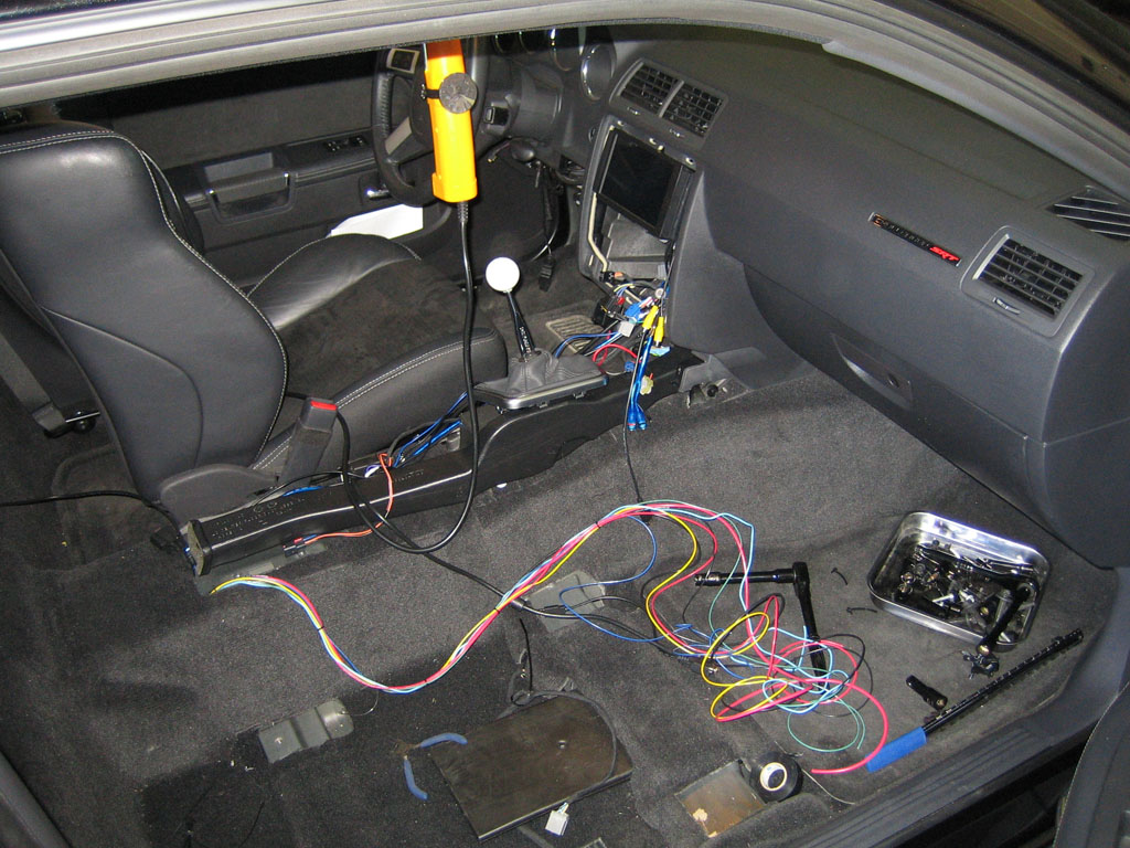
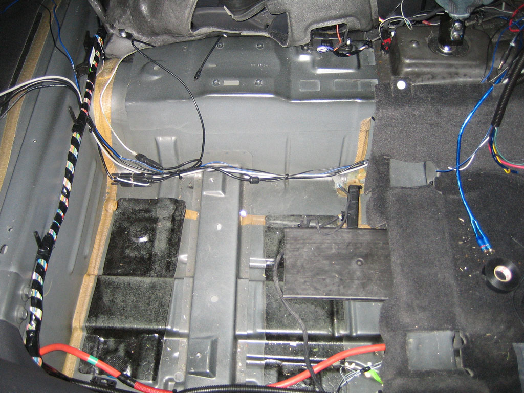
Started reinstalling the carputer back into the car.
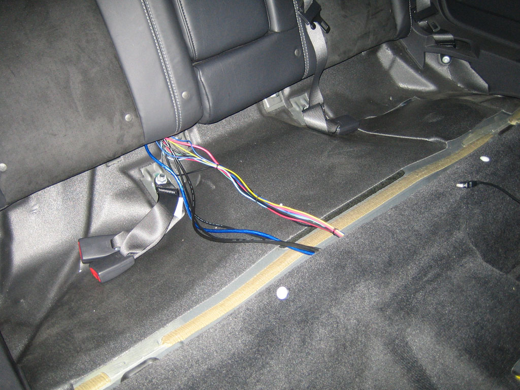
Ended up removing the seatbelt bracket so I can completely remove the carpet out of the way. Makes running wires A LOT easier.
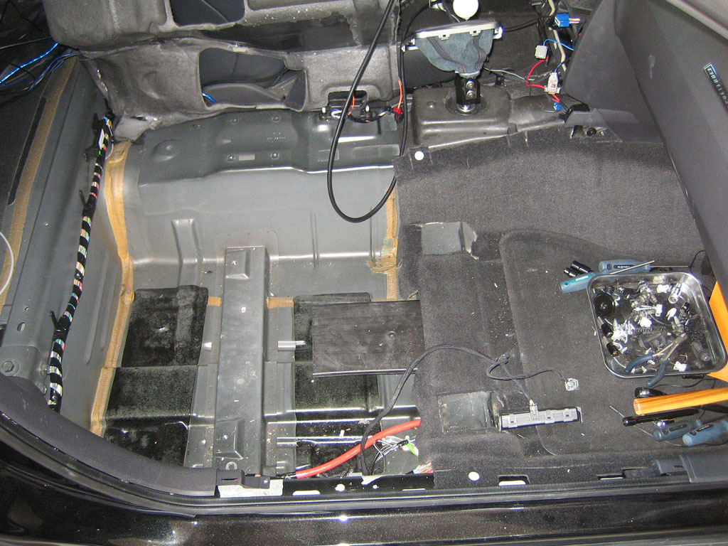
I re-routed all the power wires from going down the middle of the car to the side. Also used loom to keep them together.
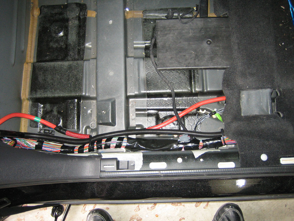
I ran the PC cables down the right side of the console. This includes Video, USB and my Reset/LED cable. Ran the Audio Cable on the left side of the console.
Left plenty of slack in the wire, There’s a lot of empty space under the seat to let the wire breathe.
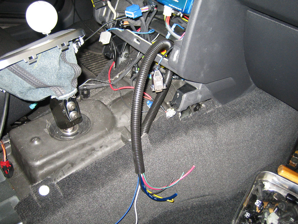
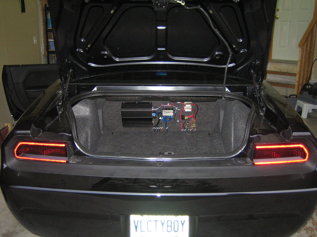
Center Console and Passenger seat back in. All wiring cleaned up though most of it not connected yet. Just the Audio/Video and USB cables.
Video of CentraFuse and GaugePod integration in action. Analog Volume control currently in the cup holder. Will have to come up with a better location for it in the future.
Update [2011-04-01]
Eureka! I’ve figured out that with the CAN bus, you can query multiple values at once. I should see a significant boost in PIDs/second once I modify the code to do so. There’s still a good chance I’ll be able to achieve a decent refresh rate on the OBD.
Update [2011-04-16]
Software Gauges
The gauges are nearly real-time with maximum sampling rates of about 60 PIDs / second. However, I also re-wrote some of the code so that some PIDs are higher priority than other, so stuff like Temperature only updates once per second where stuff like RPM updates as fast as possible. The end result is that the gauges are much smoother for stuff that changes rapidly.
Also added code to properly handle the car turning on and off and handle the carputer going to sleep and waking up. The end result is almost 100% stable gauge software. I still have some error handling to add but right now i want it to crash so that I can analyze the cause.
Once my new analog sensors arrive, I’ll wire in the Arduino and hopefully complete this phase of the project.
that is badass….very impressed…
Thanks. The car has been put away for the winter but planning a lot more stuff for it next year.